Insert

On the Structural tab, in the Plate group, the Insert menu includes tools for inserting plates whose object type is Structural Component.
After the insertion, you can manage the plate object with the tools in the Edit group of the Structural tab as well as with the tools in the Edit group of the Layout tab. You can edit the shape of the plate as described in Edit and change the plate material as described in Material.
Insert
You can insert a structural plate and freely define the direction of the plate's thickness.
Do the following:
-
Optionally, select the system for the new plate from the Model Tree pane.
-
Select Structural tab > Plate group > Insert.
-
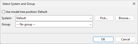
The Select System and Group dialog opens. Define the settings, and click OK.
-
System – Select a system for the model object. You can use the system currently selected in the model tree, select from the drop-down list, pick from another model object, or select from the object browser.
-
Group – Select whether to assign the model object to a group.
-
-
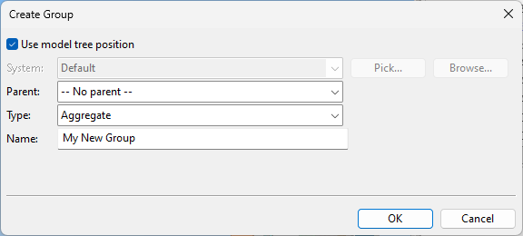
If you chose to create a new group, the Create Group dialog opens. Define the group properties, and click OK.
-
In the Plate material object browser dialog, select the plate material and thickness, and click OK.
-
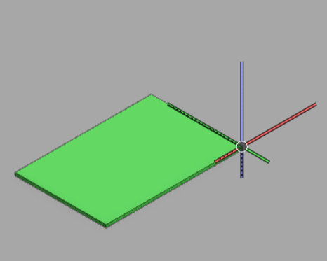
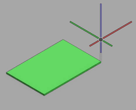
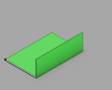
Pick the origin of the plate. (How the plate is positioned in relation to this point depends on the shape of the plate.)
-
Use the arrow keys to set the white arrow on the screen to point to the direction that the plate is to face, and press Enter.
The curve shape dialog opens.
-
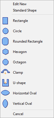
Select how to create the shape of the plate:
-
Edit New – Select this to create a completely custom-shaped plate.
-
Standard Shape – Select this to create a plate whose predefined contour cannot be modified.
-
Select one of the listed template shapes to create a plate whose contour you can modify after the insertion.
For more details on editing the shape afterward, see Edit.
-
-
You are prompted to define the parameters of the plate, such as width and height. Specify the parameters and click OK.
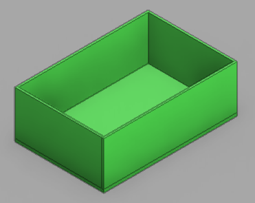
The plate is inserted in the model.
Insert towards…
You can insert a structural plate with a command that specifies the direction of the plate's thickness along a specific main axis.
Do the following:
-
Optionally, select the system for the new plate from the Model Tree pane.
-
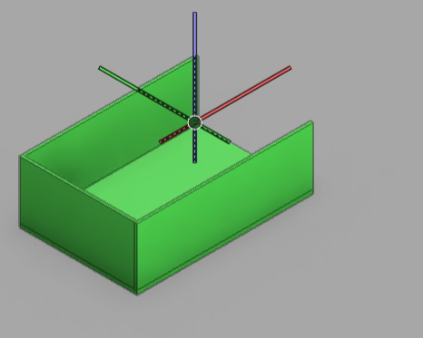
Select Structural tab > Plate group > Insert and then the appropriate command:
-
Insert towards Z+
-
Insert towards Z-
-
Insert towards X+
-
Insert towards X-
-
Insert towards Y+
-
Insert towards Y-
-
-
The Select System and Group dialog opens. Define the settings, and click OK.
-
System – Select a system for the model object. You can use the system currently selected in the model tree, select from the drop-down list, pick from another model object, or select from the object browser.
-
Group – Select whether to assign the model object to a group.
-
-
If you chose to create a new group, the Create Group dialog opens. Define the group properties, and click OK.
-
In the Plate material object browser dialog, select the plate material and thickness, and click OK.
-
Pick the origin of the plate. (How the plate is positioned in relation to this point depends on the shape of the plate.)
The curve shape dialog opens.
-
Select how to create the shape of the plate:
-
Edit New – Select this to create a completely custom-shaped plate.
-
Standard Shape – Select this to create a plate whose predefined contour cannot be modified.
-
Select one of the listed template shapes to create a plate whose contour you can modify after the insertion.
For more details on editing the shape afterward, see Edit.
-
-
You are prompted to define the parameters of the plate, such as width and height. Specify the parameters and click OK.
The plate is inserted in the model.
Route plate
You can create a series of plates along a route specified with corner points. This can be used, for example, to create the bulkheads of a compartment or the walls of a room.
Do the following:
-
Optionally, select the system for the new plate from the Model Tree pane.
-
Select Structural tab > Plate group > Insert > Route plate.
-
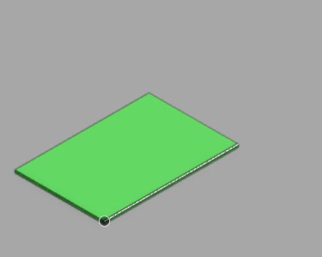
Pick the starting point of the plate to be created.
-
Pick a second point to define the plate's height.
-
Pick a third point to define the plate's width.
-
The Select System and Group dialog opens. Define the settings, and click OK.
-
System – Select a system for the model object. You can use the system currently selected in the model tree, select from the drop-down list, pick from another model object, or select from the object browser.
-
Group – Select whether to assign the model object to a group.
-
-
If you chose to create a new group, the Create Group dialog opens. Define the group properties, and click OK.
-
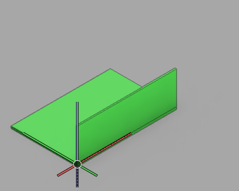
In the Plate material object browser dialog, select the plate material and thickness, and click OK. The first plate is now ready.
-
Pick the next routing point to create the second plate.
-
Continue inserting route points as required.
-
When all the plates have been inserted, press Esc to exit the tool.