Model Tree pane
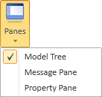
Select Home tab > Show group > Panes > Model Tree to show or hide the Model Tree pane. This pane shows the hierarchical structure of the 3D model.
Opening the model tree pane docks the pane to the left side of the application window. You can drag the pane by its title bar to detach the pane from its current position, and then either leave it floating or dock it to another part of the application window.
You can use the model tree pane for the following:
-
Search for tree items.
-
Customize the tree and filter its contents.
-
Browse and manage 3D model objects.
-
Browse and manage groups, lines, and systems.
-
Select an item to show its details in the Properties pane.
-
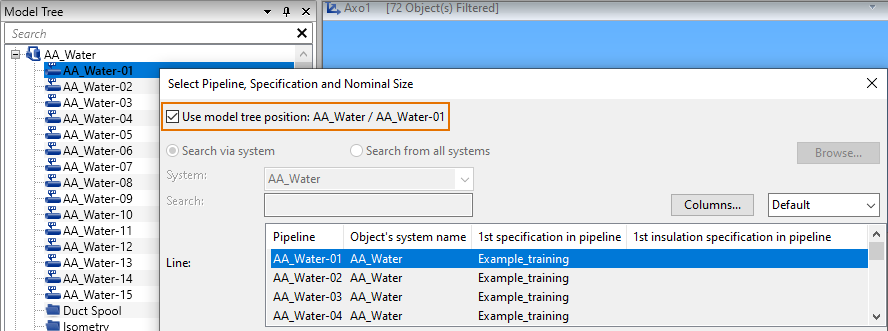
Select an item to define the context for a tool that you intend to use next.
For general information on panes in Plant Modeller, see Panes.
Searching the tree
You can search for a text string based on the following properties of the items listed in the model tree:
-
Group description
-
System name
-
Line name
-
Position ID
-
COS object ID ("obi"), which must be entered exactly as displayed in COS, including the letter case.
Do the following:
-
In the search bar of the model tree, enter the text string you want to find. Use a prefix to target specific types of items.
 Show/hide details
Use the prefix… To find… g:: groups (except lines) p:: pipelines h:: duct lines c:: cable tray lines v:: valve position IDs i:: instrument position IDs e:: equipment position IDs s:: structural position IDs Make sure you type the prefix correctly. An unrecognized prefix becomes part of the search phrase.
If the search string is… The search tries to find… water-01 any entities whose name contains "water-01" p::water-01 only pipelines whose name contains "water-01" x::water-01 any entities whose name contains "x::water-01" -
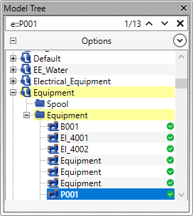
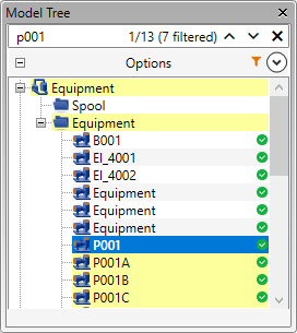
Press Enter to initiate the search. The search bar indicates the number of items that match the search, as well as those that match but are currently filtered out by Filtering the tree.
-
If there are fewer than 100 items to display, these items are highlighted in the tree and the first one is automatically selected.
-
If items matching the search cannot be displayed due to filtering, the search bar shows how many items are filtered out.
-
If no results appear, adjust the search string and try again.
-
-
Use the up/down arrows
 in the search bar to navigate between search results.
 -
Click
 in the search bar to erase the search string and clear the search results.
Other ways to locate items in the tree:
-
Using the active work view:
-
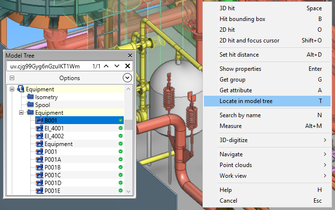
To locate a model object, right-click the object in a work view and select Locate in model tree.
-
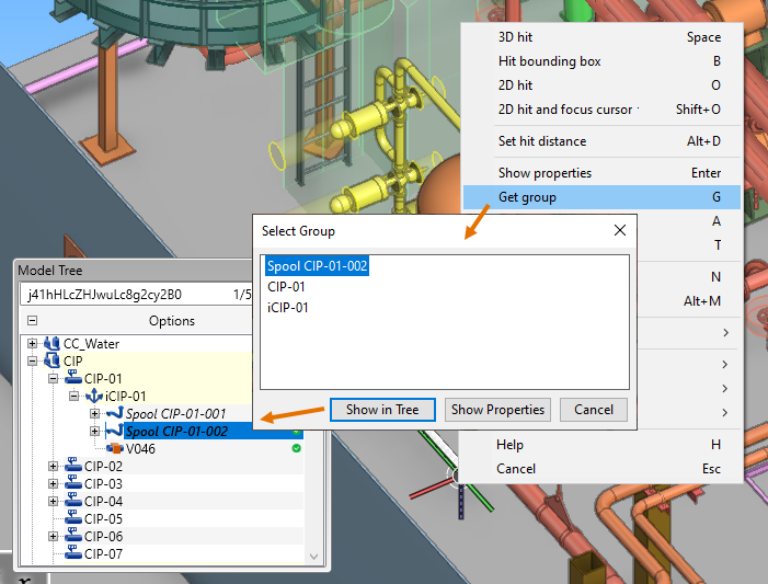
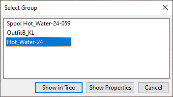
To locate a group, right-click a model object that belongs to that group and select Get group from the context menu.
Then, in the Select Group dialog, select the required group from the list and click Show in Tree.
-
-
Using the property pane:
-
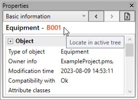
Click the name of the currently selected entity to locate it in the model tree.
-
Selecting hierarchies
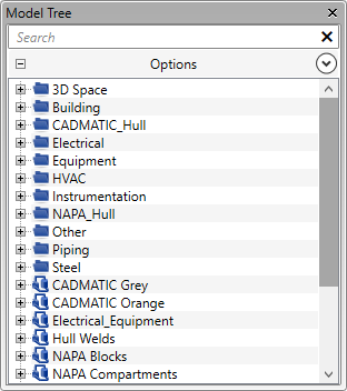
The default model tree uses the name of the system as the first level of the tree. When you expand a system branch, you can see which lines (and other entity collections) use that system.
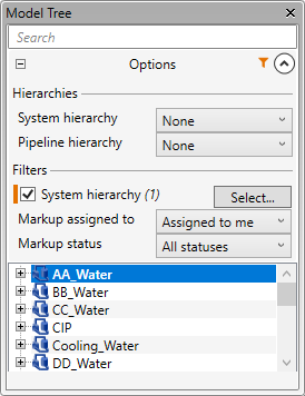
You can change the hierarchies in the Options section.
Prerequisites
-
Optionally, you can create a new hierarchy in an object browser. For example, you can create new system-based hierarchies in File > Environment > Systems and lines and new pipeline-based hierarchies in File > Environment > All library and project > [project] > Pipelines. For more information on managing hierarchies, see Hierarchies.
Note: After creating a new hierarchy, restart Plant Modeller to display the hierarchy in the model tree.
Do the following:
-
In the Model Tree pane, open the Options section by clicking
 .
. -
System hierarchy – Select how to arrange systems in the tree:
-
None – (default) Select this option to use system name as the first level of the hierarchy.
-
System types – Select this option to use system type as the first level of the hierarchy. (System name is the second level.)
-
Select a user-defined system hierarchy to arrange the model tree based on that.
Show/hide example
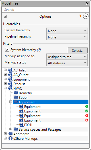
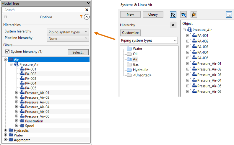
In this example, a dynamic system hierarchy called "Piping system types" is selected to arrange the pipelines based on what type of substances they are transporting, and there is a filter that hides all non-piping systems from the tree. For more information on filters, see Filtering the tree.
-
-
Piping hierarchy – Select how to arrange pipelines in the tree:
-
None – (default) Select this option to arrange the pipelines based on their name. This is the only option, unless you have created custom pipeline hierarchies.
-
Select a user-defined pipeline hierarchy to arrange the pipelines based on that.
Show/hide example
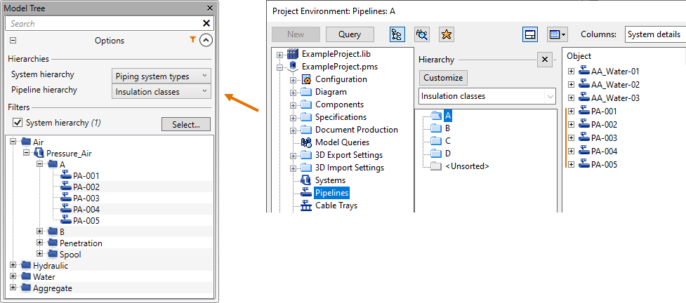
In this example, we use a dynamic hierarchy called "Insulation classes" to arrange the pipelines based on what type of insulation they require, and there is a filter that hides all non-piping systems from the tree. For more information on filters, see Filtering the tree.
-
-
Close the Options section by clicking
 .
.
Notes:
-
Groups are handled separately in the tree. User-defined groups can be found under the system they belong to. In addition, they are shown as root-level collections after all the systems. The project administrator can enable or disable the displaying of groups in the tree, as described in Model Tree.
-
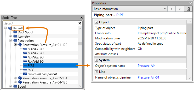
An italicized entity name indicates that the entity is being listed under the system of the group whose member it is, and not under the system that the item itself belongs to.
Show/hide image
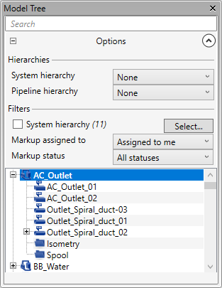
In this example, the selected 'PIPE' object is italicized because it is a member of a Penetration group that uses the 'Default' system whereas the object's system is 'Pressure_Air'.
-
The hierarchical structure of Pipelines, Isometric Groups, and Spool Groups differs from their actual structure in the model. Spool Groups associated with an Isometric Group are shown under the Isometric Group, even though they might not belong to it in the model. Pipeline isometrics are shown under the related pipeline in the tree, even though the Pipeline Group belongs to the Isometric Group in the model.
Filtering the tree
You can filter the model tree to show only the systems or markups you are interested in. The orange filter icon ![]() indicates that the tree is filtered and does not show all the items. Also, searching the tree indicates if some of the search results are filtered out.
indicates that the tree is filtered and does not show all the items. Also, searching the tree indicates if some of the search results are filtered out.
Do the following:
-
In the Model Tree pane, open the Options section by clicking
. -
You can set up and use the System hierarchy filter:
-
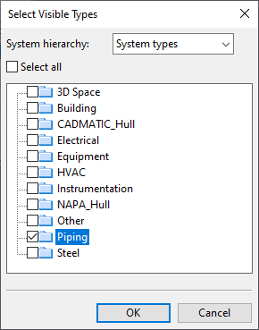
In the Filters section, click Select. The Select Visible Types dialog opens.
-
Select the system hierarchy to use, select which items to show in the tree, and click OK.
-
Enable or disable the filter as needed.
-
-
If you have eShare markups in the model tree, you can filter the list of markups:
-
Markup assigned to – Select whether to show all markups or only the markups that are assigned to you.
-
Markup status – Select whether to show markups with any status or only the ones that have a specific status.
-
-
Close the Options section by clicking
.
Managing tree items
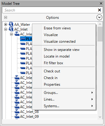
You can perform various actions in the model tree by using the following context-menu commands.
|
Command |
Description |
|---|---|
|
Hides the specified objects in all open work views. |
|
|
Visualizes the specified objects in all open work views. |
|
|
Visualizes the specified objects and the objects in the connected lines in all open work views. |
|
|
Shows the specified objects in a separate (shaded) view. |
|
|
Opens the P&ID view that contains the position ID of the selected component. If multiple diagrams contain the same position ID, you are prompted to select which one to open. See also Diagrams. |
|
|
Zooms to and highlights the entity in the active work view. |
|
|
Adds the items under the selected node to the selection. This command is not available when Classic navigation is enabled in the Input settings. |
|
|
Sets a filter box around the specified entities in the active (shaded) work view, so that only the objects that are inside the filter box are shown, and opens the Edit Filter Box dialog for adjusting the size of the filter box. For details, see Edit box (Shift+4). |
|
|
Check in |
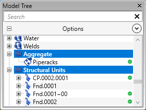
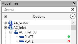
Checks out/in the specified entities. A green icon on the right indicates that the entity is currently checked out to you; a red icon indicates that the entity is checked out to another user. |
|
Opens the Properties pane, showing information on the selected object. |
|
|
Deletes the selected item, if possible. You are prompted to confirm the action or informed that the item cannot be deleted. |
|
|
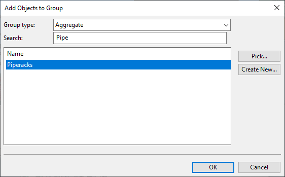
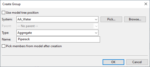
You can use groups to manage a set of objects as a single unit. Project administrator can define which group types are visible in the model tree, as described in Model Tree.
|
|
|
When the context menu is opened from a system, the commands in the Lines menu allow adding new lines to that system, and selecting one or more lines allows those lines to be deleted.
For more information, see Systems and Lines. |
|
|
When a system is selected, the commands in the System menu allow adding and deleting systems.
For more information, see Systems and Lines. |
In work views, you can find information on existing groups in several ways:
-
You can use the Get group command to see the groups that the selected object belongs to.
-
You can use the Search by name (N) command to search for a specific group by its name.
-
You can make group-based selections with Select by… Group (G) and Select by… Name (N).
Managing markups in the tree
Markups are usually created in eShare or eGo to request some changes to the 3D model. If your project is connected to eShare, you can set new markups to be loaded to your Plant Modeller area. Updating the area model shows a notification if a markup is now assigned to you, and after loading the latest markups you can select a markup from the model tree to see the given request in the property pane.
Prerequisites
-
Administrator has connected the project to eShare. See Settings and Actions.
-
You have selected the Use eShare Markups option in File > Settings > User Settings > Markups.
-
Optionally, you have set the active work view to show markup icons, as described in Filter. (Only markups that are linked to a position ID can show the icon.)
Do the following:
-
Use the Model Tree pane and the Properties pane to load markups from eShare:
-
If using automatic updating, open the eShare Markups list by clicking
 .
. -
If using manual updating, select eShare Markups in the tree and then click Update in the property pane.
The eShare Markups branch of the tree lists the loaded markups, including those that are not linked to a model object.
-
-
You can filter the markup list. Open the Options section by clicking
and change the filters as appropriate:-
Markup assigned to – Select whether to show only markups Assigned to me or All.
-
Markup status – Select whether to show only markups that have a specific status or All statuses.
-
-
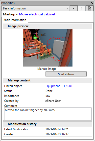
You can view the details of a markup in the Properties pane by selecting the markup from the markup list or by clicking its icon in the active work view. If you want to see the actual markup in eShare, click Start eShare.

Other ways to see markup information:
-
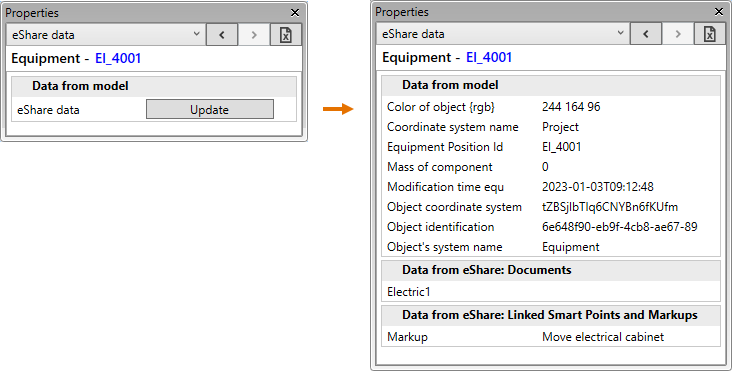
If you select a model object and click Update on the eShare data tab of the Properties pane, the markups and smart points which are linked to that object are listed in the Data from eShare: Linked Smart Points and Markups section.
Using the tree for pre-selection
You can use the model tree to pre-select the context for a Plant Modeller command or tool that you intend to use next.
For example, if you select a pipeline from the model tree and then start the pipe routing tool, you can set the new pipe to use the pipeline that is selected in the tree.