About the Support Designer
Support Designer provides tools for modeling supports for pipes, air ducts and cable trays, and for creating the associated drawings and BOM lists.
In a large process or power plant, there are usually thousands of pipe supports alone: approximately 3,000 supports in a paper mill, approximately 4,000 supports in a 600 MW fossil fuel power plant, and over 10,000 in a 1,100 MW nuclear power plant. Accordingly, the supporting of piping, ducting, and cable way systems requires significant efforts in engineering, design, fabrication, installation, and maintenance.
In a CADMATIC design project, the designing of supports can start as soon as the routes are defined. As for example stress analysis may require the routes to be changed later, this phase in detailed design is often partly iterative. Using the Support Designer, creating large amounts of supports and support drawings, and making changes to both as needed, is a much more manageable process than when supports are built profile by profile, using the normal design tools.
In the CADMATIC design tools, a pipe support is a combination of primary and secondary parts that are identified via a unique support position ID.
- Primary support is the supporting component that is directly connected to the pipe, such as a pipe clamp or a pipe slide. The primary support designates the amount of resistance the support can provide in various loading situations. (For ducts and cable trays there are usually no primary supports in the same sense as there are for pipes.)
- Secondary support is the body to which the primary parts are mounted and which connects the support structure to other structures. Typically, this is a set of structural steels that are welded together and anchored to the wall in a plant or welded to the hull steel in a ship.
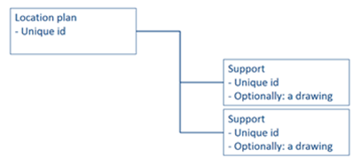
The supports are usually organized in a wider context. Their division can be based on, for example, their intended physical position in the plant or ship and/or logistics containment. In CADMATIC, we call this context the location plan. Often the location plan is published as a drawing which shows the location of each support in the area where the support will be installed.
Each support can only be a member of a single location plan. The picture below shows the basic hierarchy of location plans, using an example where two supports are assigned to the location plan.
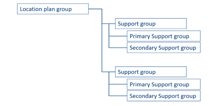
In the 3D model, this hierarchy is implemented using Plant Modeller group objects:
In the design of pipe supports, the secondary support constructions are often just dimensional variations from a small set of basic constructions. Therefore, companies often standardize the basic secondary support types, and then in the Bill of Materials they reference the in-house standard support drawing, with a few additional dimension and material parameters, to order all the materials for the supports. Also the manufacturing of standard supports is usually more cost-effective than that of custom supports. Accordingly, we recommend standard supports to be used whenever possible.
For example, in a paper mill project there are typically 30–40 different standard support drawings in use. In each project, there are also supports which are non-standard. For the custom supports, separate support drawings are made to order the materials and to show the details for manufacturing. These drawings are rather simple, but there can be a lot of them.
Support Designer includes a library of standard and custom support templates. More custom templates can be added by using scripts.
The generating of location plan and support drawings can usually be semi-automatic at least, in some cases fully automatic.