Support Designer's tools
Support Designer provides tools for managing location plans and supports.
Location plans
Supports must always be assigned to a location plan. A location plan defines the extents of a 3D box in the model area, and you can divide the model area into as many location plans as you like, depending on how you want to manage supports in different locations. A designer who is creating a new support must first select its general location by choosing a location plan for it, and the created support must fit inside the extents of the chosen location plan or the creation fails. Each support can only be assigned to a single location plan at a time, but supports can be moved from one location plan to another.
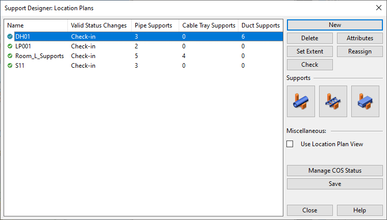
In the Support Designer: Location Plans dialog, you can add, modify, and remove location plans, and access the supports of a given location plan.
To open this dialog, select Support > Location plans on any of the following tabs: Piping, Ducting, or Cabling.
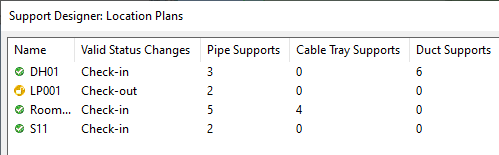
On the left side of the dialog you see a list of all location plans defined in the project. For each location plan, the list displays the name, the valid COS operations, and the number of supports it contains.
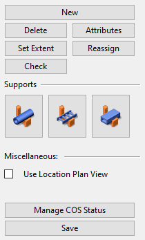
On the right side of the dialog are the tools for managing location plans.
Location plan tools
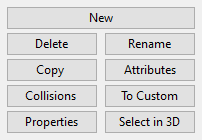
In the Support Designer: Location Plans dialog, select a location plan from the location plan list to manage it with the following tools.
|
Button |
Description |
|---|---|
|
Starts the process of creating a new location plan. See Creating location plans. |
|
|
Deletes the selected location plan. Only location plans that do not have supports can be deleted. |
|
|
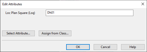
Opens the Edit Attributes dialog for assigning attributes to the Location Plan group object. See Attributes. |
|
|
Opens the Set Properties of View… dialog for adjusting the extents of the location plan in the 3D model. The supports must be completely inside this 3D box. See Set Properties of View. |
|
|
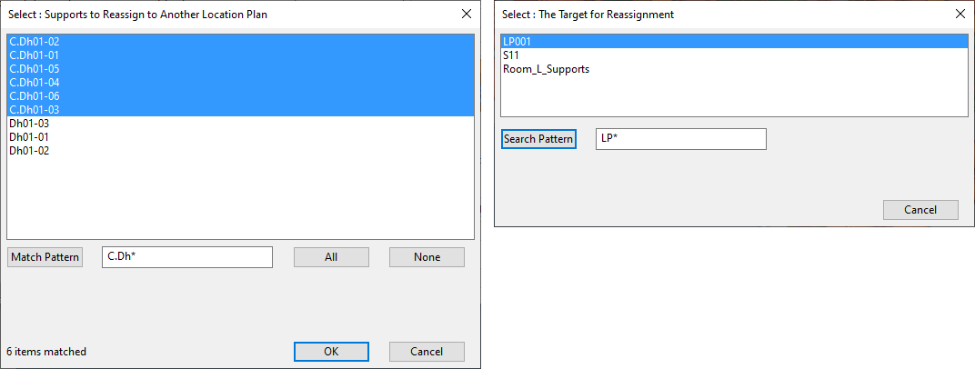
Starts the process of moving supports from one location plan to another. Tip: You cannot rename a location plan directly, but you can use the reassign function as a workaround: create a new location plan with the desired name and transfer the supports from the old location plan to the new one. |
|
|
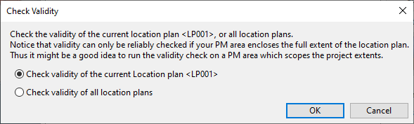
Allows you to run a validity check for the selected or all location plans. If the validity check found errors, a report opens as a text file. The report indicates, for example, if a support construction has no primary or secondary supports or if a support is not inside the designated location plan. |
|
|
Opens a dialog for managing pipe supports. See Pipe, duct, and cable tray supports. |
|
|
|
Opens a dialog for managing cable tray supports. See Pipe, duct, and cable tray supports. |
|
|
Opens a dialog for managing air duct supports. See Pipe, duct, and cable tray supports. |
|
When selected, a browser view opens showing the 3D content of all supports that are currently assigned to the selected location plan. The name of the location plan is shown in the center of the set of 3D objects in all open 3D views. |
|
|
Opens the Manage Location Plan COS Status dialog where you can check in/check out and request/relinquish the ownership of location plans and the related objects. See Managing the COS status of location plans and supports. |
|
|
Save |
Opens the Save dialog for saving the changes locally or in COS. See Saving the area model. |


Pipe, duct, and cable tray supports
You can use the Support Designer to create supports for pipes, cable trays, and air ducts. You can add, modify, and remove standard supports and custom supports, and manage the drawings of custom supports.
The design tools are used in the same way in all three disciplines, but the user interface is specific to each discipline, as indicated by the name of the dialog: Pipe Supports, Duct Supports or Cable Tray Supports.
Note: In this documentation we describe the common aspects of all three variants by referring to them as "the Supports dialog".
To open the Pipe Supports dialog, do one of the following:
-
On the Piping tab, click the Support button or select Support > Pipe supports.
-
In the Support Designer: Location Plans dialog, select a location plan and click the pipe
 button.
To open the Duct Supports dialog, do one of the following:
-
On the Ducting tab, click the Support button or select Support > Duct supports.
-
In the Support Designer: Location Plans dialog, select a location plan and click the air duct
 button.
To open the Cable Tray Supports dialog, do one of the following:
-
On the Cabling tab, click the Support button or select Support > Cable tray supports.
-
In the Support Designer: Location Plans dialog, select a location plan and click the cable tray
 button.
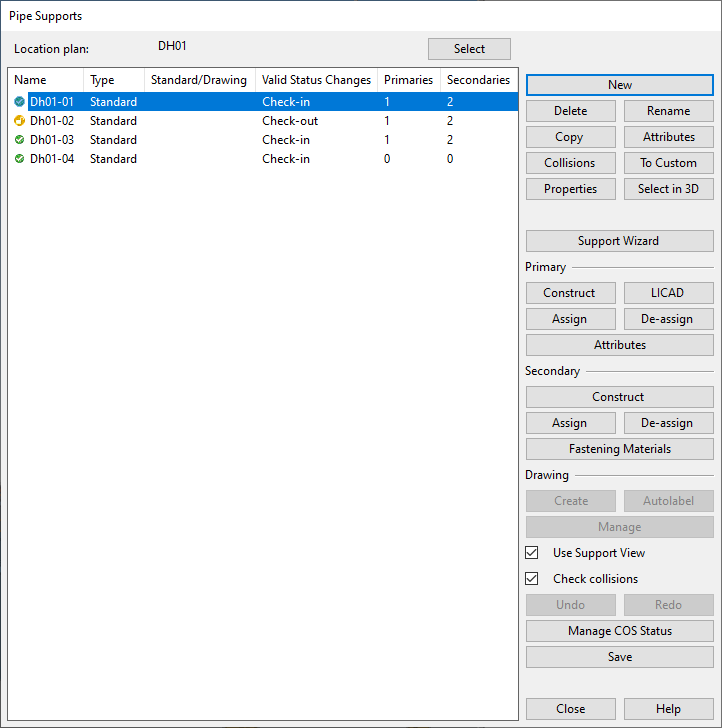
On the left side of the dialog you can see the supports of the selected location plan.
The columns of the list pane are:
|
Column |
Description |
|---|---|
|
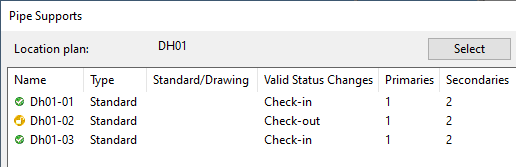
Name |
Displays the COS status and the name (unique ID) of the support group. |
|
Type |
Displays "Standard" for a standard support and "Custom" for a custom support. |
|
Standard/Drawing |
For a standard support, displays the value of the field "Drawing or standard" in the support template, as defined in the project configuration. For a custom support, displays the user-defined support drawing number. |
|
Valid Status Changes |
Displays which COS status changes are possible for the support group at the moment. |
|
Primaries |
Displays the number of objects currently assigned to the primary support group. |
|
Secondaries |
Displays the number of objects currently assigned to the secondary support group. |
On the right side of the dialog are the tools for managing supports.
Support tools
In the Supports dialog of the given discipline, you can use the following tools.
-
Tools for managing the support constructions:
 Show/hide details
Button
Description
Allows creating a new standard or custom support. See Creating supports.
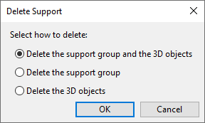
Opens a dialog for selecting whether to delete both the support group and the 3D objects (including objects created outside Support Designer) or just the support group or the 3D objects.
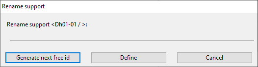
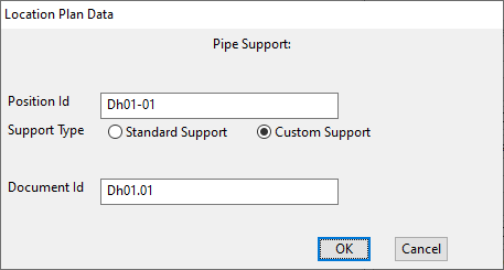
Allows changing the position ID of the support construction.
Allows creating one or more copies of the selected support.
For more information, see Creating supports by copying.
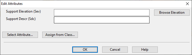
Allows assigning attributes to the selected support construction (to its support group object).
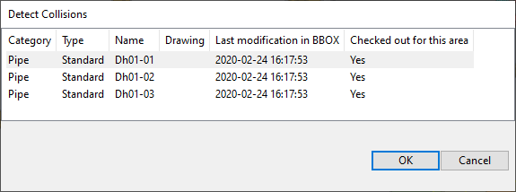
Allows detecting and browsing collisions related to support constructions.
Allows converting a standard support to a custom support. This can be useful, for example, when you have started to design a standard support but then realize that new profiles need to be added to it.
Lists the basic properties of the selected support.
Allows selecting the support list item via picking an object which is a member in one of the listed support groups.
-
Tools for managing the primary and secondary parts of support constructions:
 Show/hide details
Button/Option
Description
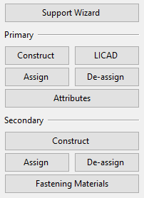
Support Wizard
Opens a tool for creating the primary and secondary parts for a new pipe support construction. In simple cases, this is all that is needed to model a support. See Creating primary and secondary supports with support wizards. Primary Construct
Opens a tool for creating and manipulating primary support objects. See Creating primary supports for pipes and Creating primary supports for ducts.
LICAD
Opens a dialog for managing integration with the LISEGA LICAD software. See Using the Support Designer with LISEGA LICAD.
Assign
Allows assigning model objects to the primary support group. This can be, for example, a pipe clamp created outside Support Designer.
De-assign
Removes selected objects from the primary support group.
Attributes
Allows assigning attributes to the primary support group.
Note: LISEGA attributes are displayed but cannot be edited here. For information on editing LISEGA attributes, see Editing the attributes of LISEGA supports.
Secondary Construct
Creates the model for the secondary support. See Creating secondary supports.
Assign
Allows assigning model objects to the secondary support group. This can be, for example, a steel structure created outside Support Designer.
De-assign
Removes selected objects from the secondary support group.
Allows adding fastening materials like bolts and nuts to the secondary support group. See Managing the fastening materials of supports.
-
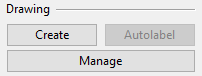
Tools for managing the support drawings of custom supports:
-
If the custom support has no drawing yet:
-
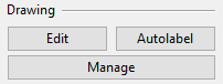
If the custom support has a drawing:
Note: The Drawing buttons are always disabled for Standard supports as their drawings are made by the support manufacturer.
Show/hide details
Button/Option
Description
If the support drawing has not been created yet, the Create button starts a guided process where you create the drawing and then it opens for editing in the Document editor.
If the support drawing already exists, the Edit button opens the drawing for editing.
Starts a guided process for generating and assigning part numbers to the objects in the BOM and generating part number labels to the primary and secondary supports in the drawing views.
Opens the Manage Drawings dialog of Plant Modeller.
-
-
Miscellaneous tools:
 Show/hide details
Button/Option
Description
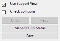
If selected, the selected support is shown in a separate view.
The support objects are shown in X-ray mode, and the neighboring objects are shown as transparent. The view is a normal, shaded work view that can be freely rotated. The support ID is displayed as an overlay text at the center of the support in all open work views.
Check collisions
If selected, supports are automatically checked for collisions.
You can clear the option if the automatic testing is impacting your ability to work and you would rather run the collision tests at a more convenient time.
For more details, see Collision checking for supports.
Select to undo the latest action.*
Select to redo the latest action.*
Manage COS Status
Opens the Manage COS Status dialog. See Managing the COS status of location plans and supports.
Save
Opens the Save dialog for saving the changes, both locally and to COS.*
* About Undo/Redo
-
Undo/redo actions do not apply to drawings. A custom support may have a custom drawing that is associated to the support via its name. If you delete a custom support that has an associated support drawing, then also the drawing gets deleted. If you then undo the deletion, the support (that is, the support group and its contents) is restored but the drawing is not.
-
Save resets the undo/redo buffer and disables the Undo and Redo buttons.
-
Construct secondary implements its own internal undo/redo functionality.
-

Construct secondary
In the Supports dialog, the Construct button in the Secondary section opens the Construct Secondary dialog where you can add, modify, and remove secondary supports.
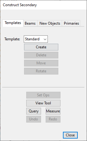
The dialog includes the following tools.
Templates
You can construct a secondary support using a ready-made template defined by the project administrator.

|
Button/Option |
Description |
|---|---|
|
Template |
Select whether to use a Standard or Custom template. |
|
Create |
Allows creating a secondary support. For an example, see Creating secondary supports. |
|
Delete |
Deletes the secondary support. |
|
Move |
Allows moving a secondary support. |
|
Rotate |
Allows rotating a secondary support. |
Beams
You can construct a secondary support by using beam insertion and modification tools.
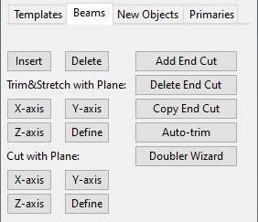
For more information on these tools, see Beam.
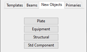
New Objects
You can insert new objects to a secondary support from the library or project database.
|
Button/Option |
Description |
|---|---|
|
Plate |
Select to insert a plate as a Standard Component to the secondary support. |
|
Equipment |
Select to insert a piece of Equipment to the secondary support. |
|
Structural |
Select to insert a Structural to the secondary support. |
|
Std Component |
Select to insert a Standard Component to the secondary support. |
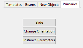
Primaries
You can edit primary supports so that they align with the secondary support.
|
Button/Option |
Description |
|---|---|
|
Slide |
Select to slide a primary support object along the pipe run. |
|
Change Orientation |
Select to change the orientation of a primary support object. |
|
Instance Parameters |
Select to edit the instance parameters of a primary support object. |
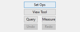
Common Tools
The Construct Secondary dialog always shows these tools, regardless of which tab is selected.
|
Button/Option |
Description |
|---|---|
|
Set Ops |
Opens the Set Operations dialog. See Set operation tool. |
|
View Tool |
Allows changing the properties of a selected view. See Set Properties of View. |
|
Query |
Opens the Object properties dialog. |
|
Measure |
Opens the Measure tool. See Measure. |
|
Undo / Redo |
Undo / redo the latest action. |