LINETYPE
There are many different linetypes to be used in drawings. Linetypes are defined in linetype files. You can define linetypes yourself by editing the linetype files, or by creating new linetype files. The default linetype file Cads.ltyincludes three versions of each linetype: short, normal and long. These three versions vary only by their length. Linetypes are printed just as they appear on the screen.
Using linetypes
When you start a new drawing, only linetypes CONTINUOUS, SYMBOL and LAYER are loaded. When using a linetype the first time, it will be loaded into the drawing. After loading, it will remain in the drawing.
Every object is drawn with a linetype. The current linetype can be set in the properties window when no objects are selected, or from the linetype list in the Basic 1 toolbar.

If the desired linetype has not yet been used in the drawing it is not listed in the linetype list. You can then find it by selecting Other linetype. Linetypes can also be set and managed in the linetype dialog (Tools > Linetype > Linetype).
Changing the linetype of an object can be done easily by first selecting it (grip edit) and then changing it directly from the linetype list in the toolbar or the property window.
By symbol linetype
Linetype SYMBOL can be used when creating a symbol. If you draw i.e. lines using linetype DASHED and save them to a symbol, those lines are always shown in linetype DASHED. If those lines are drawn using line type SYMBOL the lines are shown in the same linetype that the inserted symbol has.
By layer linetype
When using linetype LAYER the object gets its line type from the layer it is on. If the linetype of the layer is changed also the object's linetype is changed.
Linetype scale factor
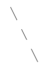
The linetype scale factor is used to define the "size" of a linetype. For example, with the dashed linetype it scales the empty and solid parts. Linetype scale factor affects all linetypes in the drawing. If the linetype scale is too small the parts of the line are so close to each other that the linetype cannot be seen anymore. By setting the linetype scaling to value 2, for example, the linetype is scaled by 2:
|
Original: |
Scaled with factor 2: |
|
|
|
Select Tools > Linetype > Linetype, and enter linetype scale.
Linetype definitions
Linetypes are defined in a linetype definition file. The default linetype definition file is CADS.LTY. You can create your own linetypes, or edit the existing ones. Linetype definition files are text files that can be edited with a text editor. Linetypes are printed exactly as they appear on the display.
The system variable LTFILE contains the names of the files, from which program looks for linetype definitions.
Linetype syntax consists of the following:
Linetype name starting with a * character.
Optional description.
Sequence definition expresses the line segments and the gaps in drawing units, separated by a comma (,). A positive line segment value means a line, negative a gap. Zero means a dot.
Draw a dash-dot line, line segment 2 du and gaps 1 du long.
*DASHDOT, Dashdot
2,-1,0,-1
Draw a dotted line, a dot every 5 du.
*DOTTED, Dotted
0,-5
Dashed line with the character X placed on each gap with the text style STANDARD.
*X, - X - X - X - X -
6,-2,["X",STANDARD,x=-1,y=-1,s=2],-2
Note: You must start with a line segment or a dot, i.e. the first sequence value must be positive or 0.
The program will automatically stretch the first and the last segments, if the linetype definition does not fit the line length.

