| Single-line tab > Other functions group > |
| Single-line tab > Other functions group > |
| Schematics tab > Other functions group > |
| Schematics tab > Other functions group > |
You can generate drawings from circuits by linking data between the project database and template drawings. This data can be created with the Electrical application or imported from another project.
Generation of schemas is based on circuits defined in the project database. For every circuit, you can define up to ten template drawings to use in generation. References to circuit devices are made with order number in device information. Circuits are created in the Electrical DB tool.
To achieve the best results, the template drawing must be a multi-line drawing into which devices, wirings, boundaries, etc. have been created with the respective functions in Electrical. The From and To information of wirings should be made in the right direction from field devices to upper level on hierarchy. Template drawings are configured in circuit information in the Electrical DB tool.
Link circuit data to a template
Before generation, you need to define the linkage between circuit data and a template drawing.
Do the following:
-
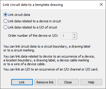
Start by selecting Define circuit data links to elements in template drawing. The Link circuit data to a template drawing dialog opens.
-
Select what to link:
-
Link circuit data – Typically, the circuit data link is used to define circuit boundaries, drawing label or circuit marking.
-
Link data related to a device in circuit – Linking a device in a circuit is typically used to link device occurrences, location boundaries, labels, device cables or device cable wires.
It is not necessary to link all data, especially for wires. The links are automatically found from the linked device occurrence wirings. The other devices along the route are also automatically found.
A label can be given the desired location information via a link to a device. If the label has circuit attributes, circuit data will also be assigned for the label.
The order number defines which circuit device is to be linked. The order number is defined in Electrical DB tool, device information.
-
Link data related to a I/O of circuit – With this option, you can link to an I/O channel or an I/O card. The order number defines which circuit I/O is to be linked. The order number is defined in Electrical DB tool, I/O information.
-
-
Click Link.
-
Select the symbols you want to link.
You can remove links with Remove link. The function indicates all elements that are linked. You can select multiple elements.
Set template directory
Template drawings will be searched from the location set in the project settings/default project settings:
-
If the active document has been added to a project, the location is set in project settings.
 Show/hide details
In the Electrical window, click the
 button. In the Generate drawings section, define the directory in the Location of template drawings/modules field.
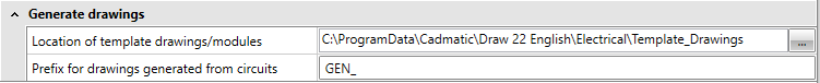
-
If the active document has not been added to a project, the location is set in the default project settings: Electrical tab > Settings group > Electrical, then select the General tab and click Default project settings.
Generate schemas
Do the following:
-
Begin generation of schemas by selecting Generate schemas based on circuit data and template drawings. The Generate drawing of circuits based on template drawings dialog opens.
-
Select the circuits you want to generate. You can use the Ctrl and Shift keys to select multiple rows, All to select all or None to clear selections.
-
Select the generation method:
-
If circuit has multiple templates, create one drawing with sheets: Circuits will be generated to a single drawing with multiple sheets (layers).
-
If circuit has multiple templates, create separate drawings from each: Separate drawing is generated from every template drawing defined in circuit settings. Different drawings will be separated with running number, for example GEN_CC-130_1, GEN_CC-130_2, etc.
-
Generated drawings:
-
Add generated drawings to project's database: After the generation is completed the drawings will be added to project and data is added to database. If you are unsure if the generation will be correct, you should disable this and add drawings manually to project after you have verified that the generation was successful.
-
Add generated drawings to CADMATIC DM's active project: If original drawing is opened from Electrical DM, this setting is enabled. If selected, the new generated schemas are added to active project.
-
Approve settings and begin schema generation by pressing OK.
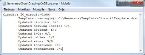
After the generation of schemas, you'll get a status message. If you want to see more detailed info about the changes made to drawings by generation, select Open log file of data updated to template drawings.
Example of a log file from schema generation: