Edit properties of individual devices
When you select a device from the Electrical DB project tree, the device properties are shown on the Devices tab. You can edit the cells with white background right in the grid.
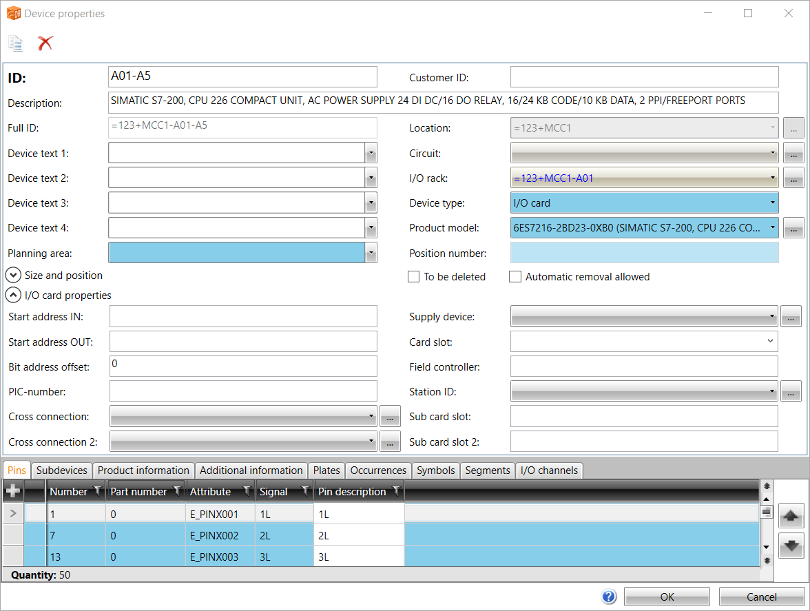
You can also edit device properties in the Device properties dialog. Open the dialog in one of the following ways:
-
In the Electrical project tree, right-click the desired device and select Edit device.
-
In Electrical DB, select the Devices tab, and double-click the first column on the desired row.
-
In Electrical DB, select the Devices tab. Then select the desired row, right-click and select Edit device.
All the changes you make are updated in all occurrences of that particular device in the project.
In the Device properties dialog, you can edit the following information:
-
ID – Device ID
-
Customer ID – Optional, free-form ID for the device that can be displayed both in drawings and reports. For information on creating customer IDs, see Create customer IDs.
-
Description – Additional information about the device recorded in a report or a drawing.
-
Full ID – Full ID is constructed from location and device ID.
-
Device text 1-4 – In the figure, attributes of the device symbol: E_SYMBTXT1-4. The texts can be edited in the drawing and the data will be updated in the database.
-
Planning area – Reports and grouping, for example, can have this piece of information as a filtering value.
-
Location – Information about where the device is located.
-
Circuit – Additional information for the device.
-
Parent device – If this is sub-device, displays next device on hierarchy.
-
Device type – Reports and grouping, for example can have this piece of information as a filtering value.
-
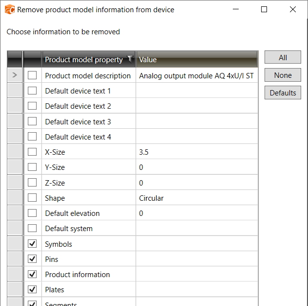
Product model – If a device has been assigned a product model, it will be displayed here. You can remove the product model from a device by selecting the empty option from the drop-down menu or by clicking the
 button. In both cases, the Remove product model information from device dialog opens and you can select the information you want to remove.
 -
Size and position
-
X-size, Y-size and Z-size – Dimensions of the device: width (X), height (Y) and depth (Z).
-
Space info – If device is located in some space.
-
Shape – Shapes define the 3D presentation of the device if 3D symbol is not defined.
-
Elevation – Elevation of the device in drawing. This affects for example 3D generation of the device.
-
System – System of the device.
-
The I/O card properties section is shown for I/O cards and other devices that have I/O card information. If the device type is something else than I/O card and the device has I/O card information, you can remove the information from the device by clicking the ![]() button in the I/O card properties section. It is not possible to remove I/O card information from the I/O card itself. For more information on I/O cards, see I/O cards.
button in the I/O card properties section. It is not possible to remove I/O card information from the I/O card itself. For more information on I/O cards, see I/O cards.
With the ![]() button, you can make a copy of the device. A new ID is assigned to the new
device. Production information, additional information and plates will
be copied to the new device.
button, you can make a copy of the device. A new ID is assigned to the new
device. Production information, additional information and plates will
be copied to the new device.
With the ![]() button, you can delete the device from the database,
but not from the drawings. The function has two settings:
button, you can delete the device from the database,
but not from the drawings. The function has two settings:
-
To be deleted – When deleting the device > Message when opening the drawing of the occurrence + visible in the tree that it was deleted.
-
Automatic removal allowed – The device created from drawing can be deleted automatically.
You can cancel editing with the Cancel button, with the cross in the top right corner of the dialog, or with the Esc key.
For more information on the tabs in the Device properties dialog, see the following:
Mass edit device properties
There are three auxiliary grids on the Devices tab on the right: Circuits, Parent devices and Locations. You can easily define device properties as a mass by dragging and dropping information from the auxiliary grids to the main grid.
You can lock the auxiliary grids to the screen from the top right corner with the ![]() button. You can also make your work easier by organizing, grouping and filtering information as you wish.
button. You can also make your work easier by organizing, grouping and filtering information as you wish.
Do the following:
-
Select the Devices tab.
-
In the main grid, select one more devices for which you want to define circuits, parent devices, or locations.
-
From the right side, click Circuits, Parent devices or Locations to open the respective auxiliary grid.
-
If necessary, organize, group and filter the information.
-
Select one or more circuits, parent devices or locations from the auxiliary grid. You can use Ctrl and Shift to select several rows.
-
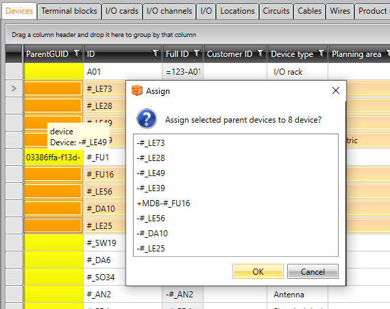
Drag the selected information to the main grid, on the corresponding column. You can only drop the information to the columns that are highlighted in yellow when you hover on the grid. The selected devices' cells are highlighted in orange in those columns. For example, if you have selected eight devices in the main grid and you drag one parent device from the auxiliary grid and hover on the main grid, the highlights in the main grid before dropping look like this:

-
Drop the information. If you selected several devices, the Assign dialog opens.

-
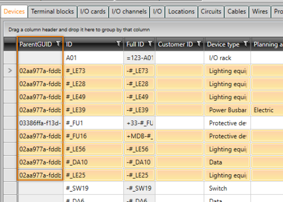
Confirm assigning the selected information to the selected devices by clicking OK. The added information is now shown in the grid.


