|
|
Layout tab > Wiring group > Edit |
With this function, you can define quantity calculation
data for the wiring, for example. You can also define wiring data while drawing wires
Do the following:
-
After starting the function, select the wirings you want to edit and press Enter. The Wiring properties dialog opens.
-
Select the cable data. Wiring data is typically fetched from the selected cable type.
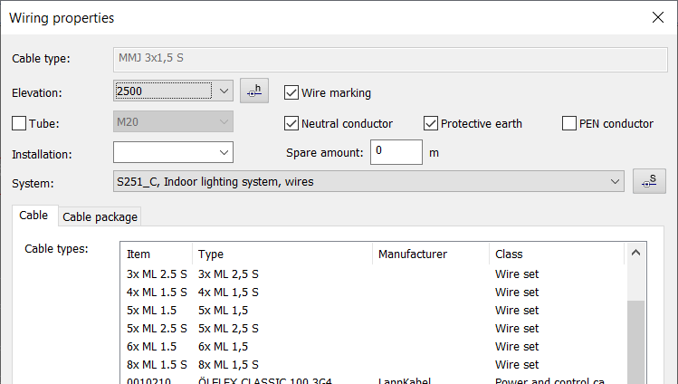
- Cable type/Description – Cable type (read only) or cable package description (editable).
- Elevation – Elevation can
be picked from drop-down menu which includes default floor and ceiling
elevations and other elevation values found in drawing. Elevation
can also be picked with elevation
pick tool by clicking the
 button.
 - Wire marking – Symbol that will be added on wiring. It indicates what type of wires are included in wiring. If wiring is very short, marking will not be added.
- Tube – Wiring tube can be selected from product database.
- Installation – Additional information about installation method. Previous values can be selected from drop-down menu.
- System – System can be selected from drop down list or picked from drawing with Pick.
- Cable / Cable package – Single wiring line can contain one or multiple cables (cable package).
- ID – Every cable has an individual ID. If ID is no given, program will generate it automatically. In case of cable packages, program will generate ID for every cable with suffix, for example W100.1, W100.2, etc.
- Used in electrotechnical calculation – Is this cable part of electrotechnical calculations. In practice this means that cables cross-sectional area will be noted in calculations.