|
|
Layout tab > Wiring group > Draw |
With this function, you can select the drawing style
During wiring, the wiring points included in the symbols are activated. Wiring point is the spot to which a wire or a cable can be connected (a real terminal in equipment). By drawing all wires and cables from one wiring point to another, you can make sure that the devices connected to the wires can be found, and the number of vertical displacements is calculated correctly.
Quantity calculation in the following image is performed by considering the wiring / tubing data and elevations as follows:

Wiring route:
Upwards from the lighting equipment (50mm), along the arc above the plug socket (about 2650mm), and then downwards to the plug socket (2300mm).
Overall length: 50mm+2650mm+2300mm=5000mm
Data for use in calculation:
-
M20 tube 5.0m
-
ML wire 15.0m
You can draw wiring between the wiring points by indicating the start and end points for the wire. You can create more complex wiring by indicating intermediate points.
Tip: While drawing, keep an eye on the command line which shows you the commands and shortcut keys you can use next.
Do the following:
-
Select the drawing style:
-
Curve – Wiring is drawn using a spline curve and constant arc radius.
While drawing, the command line shows you the commands and shortcuts you can use:
-
Change the shape of the arc with the Tab key.
-
Change the direction to which the wiring is drawn with the key combination Ctrl + <.
-
Change from curve to polyline and vice versa by entering the T command into the command line.
-
-
Polyline – Wiring is drawn using a straight multi-line and beveled endpoints, if desired.
While drawing, the command line shows you the commands and shortcuts you can use:
-
Change the angle of beveling with the Tab key.
-
Change the direction to which the wiring is drawn with the key combination Ctrl + <.
-
Draw a corner wiring by entering the corner command into the command line, or with the key combination Ctrl + F1.
-
Change from curve to polyline and vice versa by entering the T command into the command line.
-
Add end bevel 90° by entering the square command into the command line.
-
Take the wiring to a cableway by entering the route command into the command line. Then indicate the in and out points from the cableway.
-
-
Single wiring – The drawing mode prompts for start and end points for each wiring.
-
Continuous wiring – The start point of the next wiring is automatically set at the end point of the previous one. When you end one continuous wiring with Enter, the function remains active and you can draw another continuous wiring. If you press Enter when you should indicate the start point, the function is closed.
-
Star wiring –The start point of the next wiring is always set at the same wiring point as the start point of the previous wiring.
-
-
If you want to assign a specific system for the wiring, remove the check mark from the Automatic option and select the desired system from the drop-down menu or pick it from the drawing. When Automatic is selected, wiring always goes to the wiring system of the symbol from which the wiring starts.
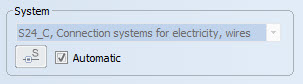
If you start wiring "from scratch" or the symbol contains no system information, wiring is set according to the default wiring system defined in the Layout settings.
-
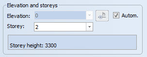
Define elevation and storeys.
- Elevation – If you want a specific elevation for the wiring, remove the check mark from the Automatic option and select the desired elevation from the drop-down menu or pick it from the drawing by clicking the
 button.
 - Storey – Select storey to wire to. If you change storey during wiring, program makes wiring references and opens the correct drawing, where you can continue wiring as usual. The Info field shows the storey description that was recorded in storey settings. If storey settings are missing or storey drawing is not added to project, storey change is not possible.
When Automatic is selected, wiring always goes to the same elevation as the symbol from which wiring is started. If required, you can apply wiring to an elevation of your choice by clearing the selection for Automatic and selecting the elevation of your choice from the list. You can also use elevation pick tool to get elevation from another element in drawing by clicking the button.
- Elevation – If you want a specific elevation for the wiring, remove the check mark from the Automatic option and select the desired elevation from the drop-down menu or pick it from the drawing by clicking the
- If you want to define wiring data (cable type, manufacturer, etc.), select Add wiring information and define the information:
- Add wiring information – If checked, the properties for the wiring to be drawn are selected in this section. For example, whether a cable or a wire is drawn, what is the type used, what is the purpose of wires, and whether the wiring marking is labeled based on this information.
- Wiring – Cable type or cable
package. You can add and edit new cables or cable packages by clicking the
 button. You can pick
wiring information from another element by clicking the arrow button.
button. You can pick
wiring information from another element by clicking the arrow button. - Wires – What kind of wires are included in cable of cable package. This affects for example wire markings.
- ID – Every cable has individual ID. If ID is no given, program will generate it automatically. In case of cable packages, program will generate ID for every cable with suffix, for example W100.1, W100.2, etc.
- Running ID – Select this, if you want the wire IDs to be consecutive.
- Installation – Additional information about installation method. Previous values can be found from drop-down menu.
- Tube – Tubing information from product database.
- Wire marking – If selected, wire marking symbol will be added to cable (not for cable packages). The wire marking is not added automatically to the wire/cable, if the wire length is only 10 x scale or shorter.
- Insert markings and symbols for the drawn wire as necessary:
- Group – Group marking is placed to the end of the wiring. Wiring information for the group is set from the wiring.
- Symbol – Symbol selected from the menu is added to the end of the wiring. This can be for example plug socket or lighting fixture.
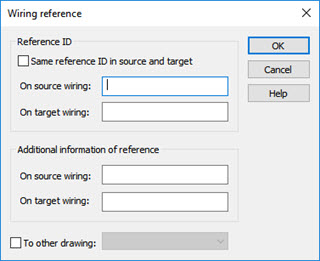
- Ref – Reference to another point in drawing or to another drawing is added to the end of the wiring. Insert wiring information to dialog that is opened. Approve information and resume wiring by pressing OK. If you have selected another drawing as target, it will be changed automatically before wiring is continued.
- Device/Loc. – Select a location/device.
Function adds reference markings to the ends of the wiring. You can move between the references by right-clicking the reference symbol and selecting Move to other end of reference.
Wiring along cableway
You can set surface wiring to pass along a cableway. By entering the route command, you can pick a point on cableway where the wiring enters the cableway and another point where wiring exits the cableway. The function draws the wiring between the selected points along the cableway by using the shortest route possible.
Hiding on intersections
Crossing wirings can be hidden from the intersections for improved readability of the drawing. Function does not cut wirings but masks another wire from the intersection with WIPEOUT -element. Functions can be found from the wirings context menu (right mouse button), Hiding on intersections.
- Hide this wiring on intersections – Hides selected wire from the intersections with other wirings.
- Set the length of the hidden part in this drawing – Sets the length of the hidden part of the wirings. Setting is saved to system variable in drawing.
- Remove hidings on intersections from this wiring – Reveals all hidden sections of the selected wire.