Draw cables
|
|
Single-line tab > Wiring group > Draw |
| Schematics tab > Wiring group > |
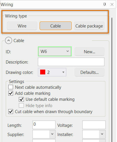
With these functions, you can draw a cable using the Wiring window. If necessary, you can also select to draw a wire or a cable package.
You can also start drawing by right-clicking Cables in the Wirings project tree and selecting Draw cable.
The From and To information is determined by the start and end point locations of the cable.
Note: Project's cable marking settings as well as Schematics-specific settings affect the drawing of cables.
Do the following:
-
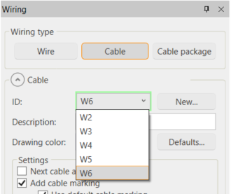
From the ID drop-down menu, select an existing cable. Alternatively, create a new cable by clicking New.
The field shows the next consecutive cable ID as a suggestion for a new cable, and the field is then highlighted with green. In the following image, the IDs W1–W5 already exist and the suggestion for the new ID is W6:
-
If desired, select a new color for the cable you are about to draw. After you have drawn the cable, the default color is reset.
You can define the default cable color in the Electrical settings. By default, the cable color is red.
-
Define the settings:
-
After the first cable, if you want to continue drawing cables with consecutive numbering, select Next cable automatically.
-
If you want to add cable marking, Add cable marking. If necessary, also define the following:
-
Use default cable marking – Select this, if you want to use the default symbol defined for cable markings in the cable marking settings.
-
Hide type info – Select this, if you want to hide the cable type information from the cable marking. The setting is enabled when the project's cable marking settingVisibility of Type in drawing has been set to According to visibility setting of symbol's attribute.
-
-
If you do not want the cable to be automatically cut when you draw across boundaries, clear the Cut cable when drawn through boundary selection. By default, cables are always cut when drawn across boundaries.
-
-
Insert additional information if needed.
-
If you want to select the cable type, select Cable type and then the type from the list. Otherwise, the cable will be of type undefined.
You can find the desired type easily by filtering: enter the character strings you want the type to include in the Filter field. The list of cable types only shows the cable types that include all the character strings you enter:

-
Indicate the cable start and end points.
-
End the cable by right-clicking or with Enter. The Wiring reference dialog opens, unless you end the line on a device or location boundary line.
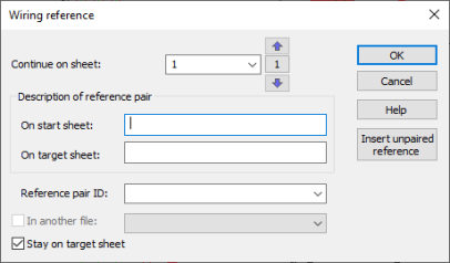
The Continue on sheet field shows the current sheet. The start sheet is shown between the arrow buttons.
-
Define the sheet where to continue the cable.
-
You can move to the next sheet with the
 button or the PageUp key.
 -
You can move to the previous sheet with the
 button or the PageDown key.
 -
You can select the desired sheet from the drop-down menu.
The sheet changes in the background according to your selection.
Alternatively, continue the cable in another open drawing by selecting In another file and then the desired drawing from the drop-down menu. The function then marks wiring references to both drawings. The reference contains the number of the drawing where the cable continues. If no drawing number is defined or it cannot be read from the drawing label, the reference will include the name of the drawing file.
You can also create an unpaired reference with the Insert unpaired reference button. For more information on unpaired references, see Manage unpaired references.
-
-
Enter free-form descriptions for the reference pair to specify where the cable comes from and where it is going to. If something else than Free text has been selected for Cable: Remote-end description in the wiring reference settings, the fields cannot be edited.
In addition, you can do the following:
-
You can select the wiring reference pair ID from the Reference pair ID drop-down menu.
-
If you select Stay on target sheet, you will stay on the target sheet after the cable has been drawn. Otherwise you will return to the sheet you started from.
-
-
Click OK.
The cable's From and To information are determined by the start and end point locations.
If the Schematics-specific setting Show the wiring dialog on modifying is enabled, clicking a cable in the drawing opens the Wiring window.
Redraw cable
You can redraw an existing cable with existing cable data. In some cases this is easier than editing a complex cable.
Right-click the cable, and select Redraw cable.
Draw the cable in the same way as a normal cable.
Unpaired references
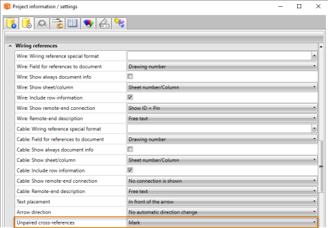
You can mark a reference on the start sheet, and then continue it later on the target sheet i.e. create an unpaired reference. To enable the Draw unpaired reference button in the Wiring reference dialog, the drawing must be part of a project and the Unpaired cross-references setting must be set to Mark in project settings.
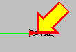
An unpaired reference looks like this:

You can select one or more references from the drawing, and then define them a pair.
Select an unpaired reference and define a pair for it in one of the following ways:
-
Select an unpaired reference.
-
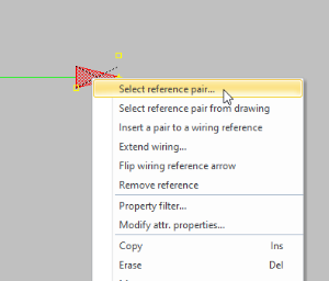
Right-click the reference, and select Select reference pair.
- Double-click the desired reference. Alternatively, select the reference, and click OK.
The Select unpaired reference dialog opens. There must be an unpaired reference on the target sheet in order for the unpaired reference to be shown in the dialog and for it to be possible to select the reference.
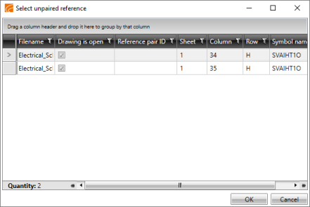
In addition to another unpaired reference, you can pair an unpaired reference with a paired reference. You cannot, however, start pairing from the paired reference. If necessary, you can disconnect the pair first and then create a new pair.
Do the following:
-
Select an unpaired reference.
-
Right-click the reference, and select Select reference pair from drawing. The reference that will be paired is indicated with a yellow arrow.
- Select an unpaired or a paired reference from the drawing. If you select a paired reference, the earlier pairing is disconnected but the wire information of the old pair will remain at the other end.
Do the following:
-
Select an unpaired reference.
-
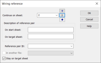
Right-click the reference, and select Insert a pair to a wiring reference. The Wiring reference dialog opens.
-
Define the sheet where to continue the cable.
-
You can move to the next sheet with the
button or the PageUp key. -
You can move to the previous sheet with the
button or the PageDown key. -
You can select the desired sheet from the drop-down menu.
Alternatively, continue the cable in another open drawing by selecting In another file and then the desired drawing from the drop-down menu. This is only possible between open drawings in the same project folder. The function then marks wiring references to both drawings. The reference contains the number of the drawing where the cable continues. If no drawing number is defined or it cannot be read from the drawing label, the reference will include the name of the drawing file.
-
-
Enter free-form descriptions for the reference pair to specify where the cable comes from and where it is going to. If something else than Free text has been selected for Remote-end description in the wiring reference settings, the fields cannot be edited.
In addition, you can do the following:
-
You can select the wiring reference pair ID from the Reference pair ID drop-down menu, or enter it in the field.
-
If you select Stay on target sheet, you will stay on the target sheet after the cable has been drawn. Otherwise you will return to the sheet you started from.
-
-
Click OK. The application goes to the sheet you defined.
-
Draw the wire by indicating the start and end points.
The Continue on sheet field shows the current sheet. The start sheet is shown between the arrow buttons.
Select several unpaired references and define pairs for them in one of the following ways:
In addition to another unpaired reference, you can pair an unpaired reference with a paired reference. You cannot, however, start pairing from the paired reference. If necessary, you can disconnect the pair first and then create a new pair.
Do the following:
-
Select at least two unpaired references.
-
Right-click one of the references you selected, and select Select reference pair from drawing (one by one). The reference that will be paired is indicated with a yellow arrow.
-
Select an unpaired or a paired reference from the drawing. If you select a paired reference, the earlier pairing is disconnected but the wire information of the old pair will remain at the other end. The yellow arrow moves to the next reference you selected.
-
Repeat step 3 until you have defined a pair for all the references you selected.
In addition to another unpaired reference, you can pair an unpaired reference with a paired reference. You cannot, however, start pairing from the paired reference. If necessary, you can disconnect the pair first and then create a new pair.
Do the following:
-
Select at least two unpaired references.
-
Right-click one of the references you selected, and select Select reference pair from drawing (several).
-
Select the reference pair, and accept with Enter. If you selected paired references, the earlier pairings are disconnected but the wire information of the old pairs will remain at the other end.