Bevel Generator
Tools > Bevel Generator

The Bevel Generator function adds bevels automatically by determining the weld lengths, where possible.
-
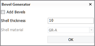
When Add Bevels is selected, bevels are determined and placed automatically where possible, but not at positions where manually placed welds are already present. Enter the average thickness of the shell plates, and select the shell material.
-
When Add Bevels is not selected, only the weld lengths and section border weld lengths are determined.
Bevels are placed where plates border other plates or shell plates. These borders are determined by plate relations.
For plates split by seams (panels), Bevel Generator takes the plate part properties (thickness and material) into account when adding bevels on seams, slots/splitters and for the ends of pillars, profiles, shell frames and face plates. Seams between plate parts get a bevel on both sides of the seam. Slots/splitters get bevels the same way as seams. See Bevels on plates split by seams.
The presentation of bevels can be set to show bevel models or bevel texts, or show nothing at all. This can be done in the System Management application, Presentation > Bevel > Settings.
Bevels on intersecting plates are shown by a triangle at the molded side of the plates. These bevels can be modified or deleted by using Construction > Bevels > Modify > Bevels, or Construction > General > Remove, respectively.
See also:
Welds
The relations of the plates determine if the welds will be placed automatically. If a plate is related to another plate without a parallel distance, or to the shell, then the welds are placed automatically.
The weld type and properties are defined by the weld configuration files. It is possible to switch an automatically placed weld symbol to a manually placed one by using the function Construction > Modify > Bevels > Modify Bevels.
The logistical data fields Generalweldlength and Blockseamweldlength need to be present for automatic welds. These can be set in the System Management application, under Logistical Database Layout.
- Blockseamweldlength is the weld length which is called upon at positions where parts are related to another block.
- Generalweldlength is the weld length called upon when the parts are not bordering another block.
Weld lines in plates split by seams
Weld lines are created for each plate part contour which is delimited by a seam, slot/splitter or plate edge. The generated weld information (weld method, throat height) is based on the properties of the plate parts.