Plate beveling rules
Predefined bevels can be added automatically to plate connections, following a system of rules.
The plate must meet the following conditions for the rules to be applied:
-
There is a relation to a plate in plan view, to a plate in cross section, or to a hull line.
Note: For relations to plates in cross section, automatic beveling only applies to complete and 1 vector relation types. Relations to plates in cross section which are of the end point relation type will not get automatic bevels. See Relation properties for information on the relation types.
-
The relation has some length.
-
No parallel distance has been set.
-
There is no knuckle present between the two plates.
This is also true for shell plates, except that shell plates can only have bevels specified for relations to plates in plan view.
The method of defining the plate bevel rules is similar to defining profile bevel rules, see Profile beveling rules.
Note: About using functions: The rule system allows for functions to be used in plate beveling rules, although there are no known uses cases to do so. Using the functions is not covered in this help topic. For information on the available functions, see Functions.
Rules for specific connection types
By default a set of rules is defined for the following specific connection types:
-
Plates related to plates or plates in plan view (planar connections)
-
Plates related to plates in cross section (non-planar connections)
-
Connections to the shell
In addition, there is a general predefined bevel rule. This rule defines which set of rules is used for the different connection types.
The rules defined in the System Management application are stored in configuration files which are located in \norms\cvar\weld folder of the active norms, as follows:
| Configuration file | Contains |
|---|---|
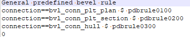
| pdbrule0000.cfg | General predefined bevel rule |
| pdbrule0100.cfg | Rules for plates related to plates in plan view |
| pdbrule0200.cfg | Rules for plates related to plates in cross section |
| pdbrule0300.cfg | Rules for connections to the shell |
The rule files can be edited manually. Manual editing is needed if the line contains more than 132 characters. Lines containing more than 132 characters cannot be edited in the System Management application. The system shows a warning if a line exceeds 132 characters.
For information on how to define rules in general, see Rule configuration files. See also Defining rules in System Management.
Defining the rules for bevels on plates
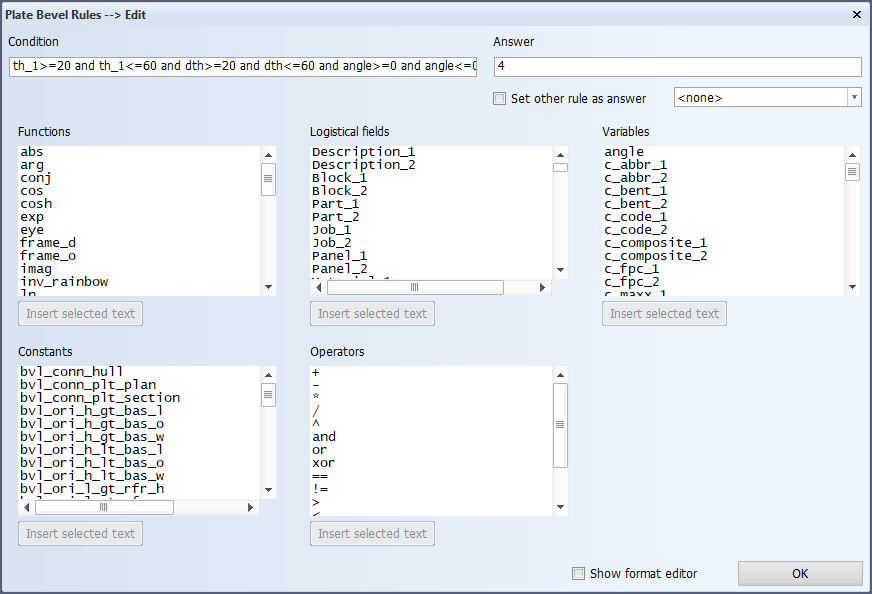
The bevel rules are defined in System Management > Construction > Welds/Bevels > Plate Bevel Rules.
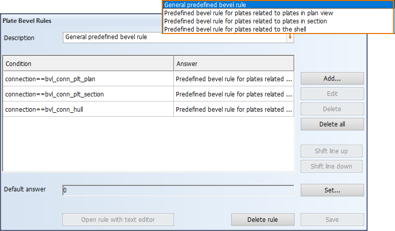
Defining the general predefined bevel rule
This is the main rule defining which are the rules used for the different connection types.
Do the following:
-
To add a new rule to the rule set, click Add. The Plate Bevel Rules > Add dialog opens.
To edit an existing rule, select the rule (line), and click Edit. The Plate Bevel Rules > Edit dialog opens.
The add and edit dialogs are similar.
-
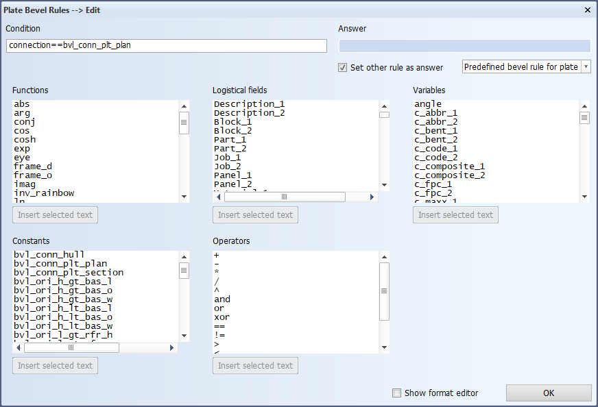
Make the following selections, and after each selection click Insert selected text. The selection is added to the Condition field. You can also directly type in text in the field.
-
From the Variables list, select one of the following:
-
connection – Type of the connection (plan view, cross section, hull)
Constant values for the connection variable
 Show/hide
Constant Connection bvl_conn_hull to the hull bvl_conn_plt_plan between plates in plan view bvl_conn_section between a plate in plan view and a plate in cross section -
orientation – Orientation of the plate edge to be beveled
Constant values for the orientation variable
Show/hide
Constant Plate plane Edge position Edge orientation bvl_ori_l_lt_rfr_h Fixed length Before reverse frame Fixed height 
bvl_ori_l_lt_rfr_w Fixed length Before reverse frame Fixed width 
bvl_ori_l_lt_rfr_o Fixed length Before reverse frame Slanted 
bvl_ori_l_gt_rfr_h Fixed length Beyond reverse frame Fixed height 
bvl_ori_l_gt_rfr_w Fixed length Beyond reverse frame Fixed width 
bvl_ori_l_gt_rfr_o Fixed length Beyond reverse frame Slanted 
bvl_ori_w_lt_mid_h Fixed width Portside Fixed height 
bvl_ori_w_lt_mid_l Fixed width Portside Fixed length 
bvl_ori_w_lt_mid_o Fixed width Portside Slanted 
bvl_ori_w_gt_mid_h Fixed width Starboard Fixed height 
bvl_ori_w_gt_mid_l Fixed width Starboard Fixed length 
bvl_ori_w_gt_mid_o Fixed width Starboard Slanted 
bvl_ori_h_lt_bas_w Fixed height Below base Fixed width 
bvl_ori_h_lt_bas_l Fixed height Below base Fixed length 
bvl_ori_h_lt_bas_o Fixed height Below base Slanted 
bvl_ori_h_gt_bas_w Fixed height Above base Fixed width 
bvl_ori_h_gt_bas_l Fixed height Above base Fixed length 
bvl_ori_h_gt_bas_o Fixed height Above base Slanted 
-
angle – Angle between the two involved parts. The angle variable can be defined as:
-
A minimum angle: angle>=
-
A maximum angle: angle<=
-
A range (min-max): angle>= and angle<=
See Angles in the different connections below.
-
-
-
From the Operators list, select the desired operator.
-
From the Constants list, select the desired value for the variable.
-
-
Click OK.
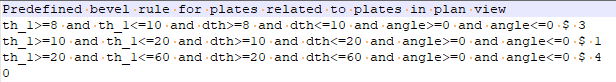
The definitions in the corresponding configuration file pdbrule0000.cfg are (by default) as follows:
Defining bevel rules for the different connections
The bevel rules for all the different connection types (plan view, cross section, hull) are defined in the same way and the rules have the same syntax.
Do the following:
-
To add a new rule (line), click Add. The Plate Bevel Rules > Add dialog opens.
To edit an existing rule, select the rule (line), and click Edit. The Plate Bevel Rules > Edit dialog opens.
The add and edit dialogs are similar.
-
Make the following selections, and after each selection click Insert selected text. The selection is added to the Condition field.
-
From the Variables list, select the desired variable. See About the variables below.
-
From the Operators list, select the desired operator.
-
Enter the value after the operator in the Condition field.
You can keep adding variables and operators until 132 characters. If you need to define more variables, you should split the rule into two lines, or edit the corresponding rule configuration file manually.
-
-
Click OK.
Below is an example of the definitions in a configuration file for plates related to plates in plan view.
About the variables
In the variables, first and second parts are indicated by postfixes _1 and _2, respectively:
-
In cross section, the first part is the plate that the bevel and the weld belongs to. The second part is the plate that gets connected to the first plate.
-
In plan view the first part is the plate with the smaller thickness. The second part is the plate with the larger thickness.
Variables specific to plate beveling
There are three variables to define thickness:
-
th_1 – Thickness of the first part. This is part that the weld belongs to.
-
th_2 – Thickness of the second part (must be used for connections to shell). This is the part that gets connected to the part that the weld belongs to (first part).
-
dth – Thickness difference between the first and the second part
Note: In connections to the shell, only the variables for thickness and material for the second part properties can be used.
Th edge_type variable defines the bevel edge type. It can be used for plate-to-profile connections and plate connections to plates in cross section. See Bevel edge types on connections to profiles, and Bevel edge types on connections to plates in cross section.
-
EDGE_PLAN – Edge type for plate connections to parts in plan view.
-
EDGE_ANGLE – Edge type for plate connections to parts in cross-section when the plate not in line with the part's edge (the edges are not on the same plane).
-
EDGE_STOP – Edge type for plate connections to parts in cross-section, when the plate is in line with the part's edge (the edges are on the same plane, plate stops against another plate).
The angle variable defines the angle between the two parts. The angle can be defined as:
-
A minimum angle: angle>=
-
A maximum angle: angle<=
-
A range (min-max): angle>= and angle<=
Other Variables
For information on all the available variables, see Variables.
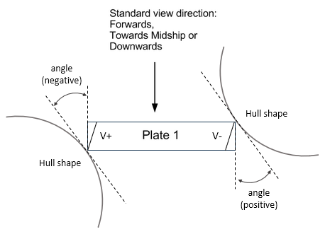
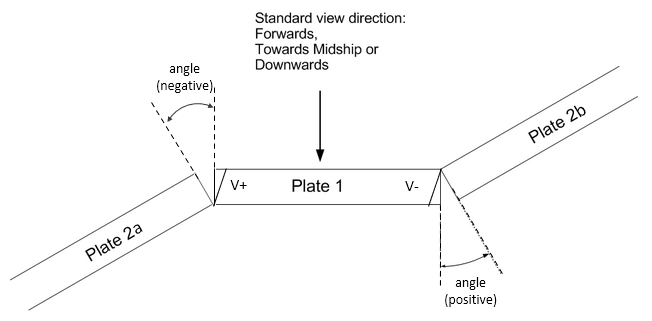
Angles in the different connections
Whether the angle between two plates is positive or negative depends on which side the angle is located relative to the view direction.
-
The angle is positive if it is located on the side opposite to the view direction (other side).
-
The angle is negative if it is located on the side of the view direction (this side).
-
For bevel types which have an opening, the angle is considered positive if the bevel opening is at the other side, and negative if the bevel opening is at this side, relative to the view direction. A relative angle can be used for these bevel types. They include all the types other than the I bevel (V+, V-, K, X, X+, X-, Y+, Y-).
The standard view directions are:
-
In length: forwards
-
In width: towards midship
-
In height: downwards
The following images illustrate the positive and negative angles in the different connection type situations.
Relation to plate in plan view
Relation to plate in cross section
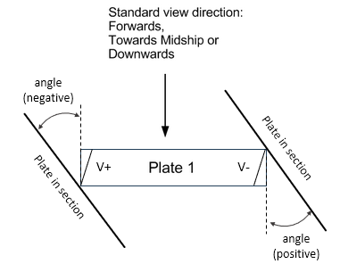
The plate in cross section can also be a shell plate.
Relation to Hull (connections to the shell)