Insert
Construction > Items > Bevels > Insert

Select from the following functions:
Bevels – Place multiple bevels on selected plates in plan view in one single action.
Single Bevel – Place a single bevel on a connection of two plates, a seam, hole or slot/splitter.
See also Inserting bevels.
Inserting a single bevel
Do the following:
-
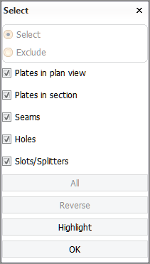
Go to Construction > Items > Bevels > Insert > Single Bevel. The Select dialog opens.
-
Select one or two plates, a seam, a hole or a slot/splitter.
In case of a plate split by seams (panel), select the desired plate part. Bevels are placed onthe edges of the plate part, not on the entire edge of the panel.
The system also creates a bevel at the adjacent plate part's edge when the edges of the plate parts are facing each other and are connected with a weld.
 Indicating the bevel placement
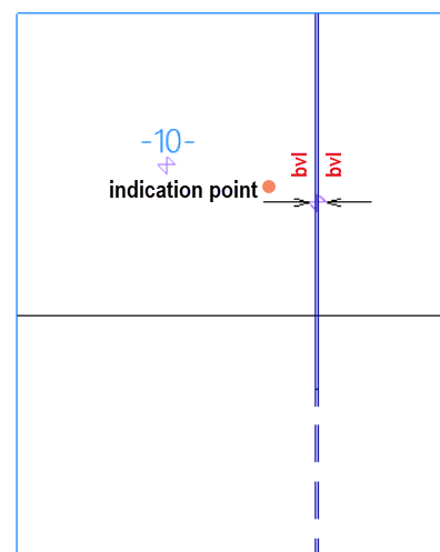
In a situation where a vertical slot/splitter spans across two plate parts which are separated by a horizontal seam, the placement of the bevel depends on the indication point.
-
To place the bevel on a plate part located above horizontal the seam, indicate right above the slot/splitter arrow.
-
To place the bevel on a plate part located below the horizontal seam, indicate right below the slot/splitter arrow.
You can also use a clump or conflict selection. The center of the clump/conflict box must be on the desired plate part, and the slot/splitter must belong to the selection. See Indicating items for information on the clump/conflict selection.
Show/hide image
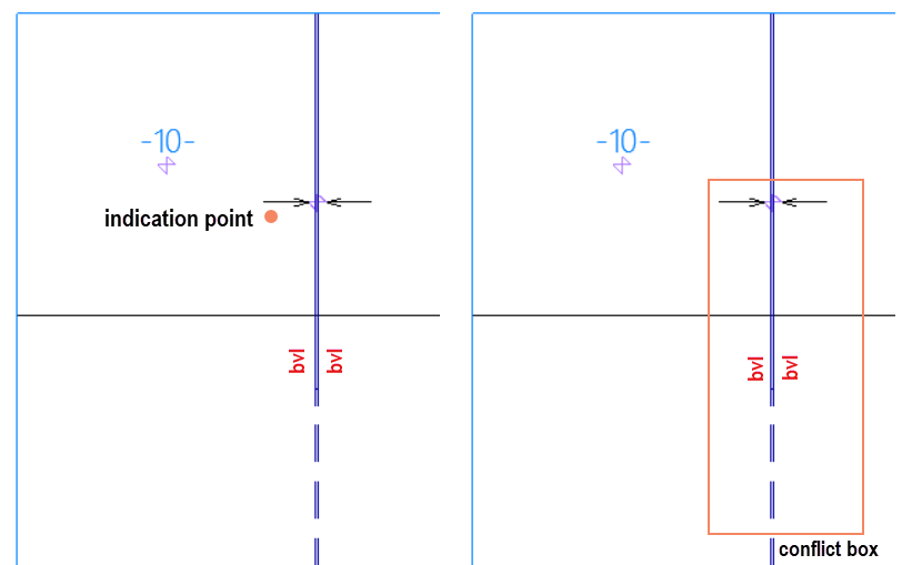
Left: Selection by indication point
Right: Selection by conflict box
Note: If significant modifications are made to the seams splitting the panel, or if the seams are modified several times, manually added bevels on the seams or on the edges of the plate parts might disappear. In some cases, the system might substitute these manually created bevels with automatically generated ones. See also Note on manual bevels on a split plate edge.
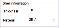
If you select the hull shape line, the Shell Information section is shown for entering the thickness and material type of the shell plating. This information is needed in cases where shell plates are involved when creating bevels.
-
-
Click OK. The Bevels dialog opens.
-
Select a predefined bevel.
Each predefined bevel has its own unique properties. You can modify the properties in the other tabs of the dialog. For more information, see Bevel properties for predefined bevels.
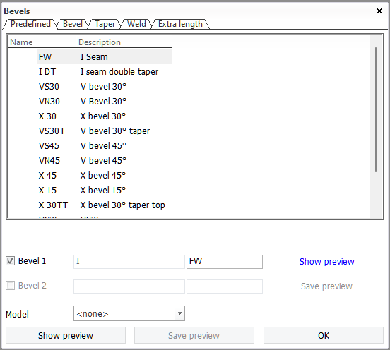
Options in the Bevels dialog
Bevel 1 / Bevel 2:
- First field – Displays the bevel text as it will appear in the active view.
- Second field – Manually influences the standard bevel code. Applicable only when the logistical field Name is used.
Model – Sets the model to be displayed for the bevels. This is optional.
Show/hide preview – Shows a preview of the bevel's appearance with the current parameters. The image in the preview is updated when a parameter is changed.
Save preview – Saves the preview to a drawing.