Chain Dimension
Draw > Dimension > Chain

Place chain dimensions. In addition to single dimensions, you can place a series of consecutive dimensions (repetitive dimensions), and a series of dimensions that have the same item as the starting point (based dimensions).

|

|

|
| Single chain dimension | Repetitive chain dimensions | Based chain dimensions |
It is also possible to place chain dimensions that are both repetitive and based.
|
| Repetitive based chain dimensions |
Placing chain dimensions
Do the following:
-
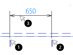
Indicate the starting point for the chain dimension.
-
Indicate the end point for the chain dimension.
You can also point to an item and press the space bar to indicate it. Use the snap keys to select a specific position on the item, such as the middle point (m). For more information, see Snap keys.
-
Indicate the position where you want to place the dimension. Repeat as many times as necessary.
-
Press Esc to stop adding dimensions.
The types of items that can be selected by indicating them in the graphical window depend on the selected selection filter. See Selection Filter below for more information.
Function dependent options are available in the hint bar at the top of the graphical window. See Hint bar.
-
Short Dimension – Activate the Short Dimension function.
-
Align – Align the new dimensions with existing dimensions. Indicate an existing short dimension or chain dimension to use as the reference point for the new dimensions.
-
Orientation – Change the text orientation of a dimension to the left, right, or middle of the dimension.
-
Move Text – Move the dimension's text to another position.
See also: Short Dimension, Indicating items, Snap keys
Chain Dimension options
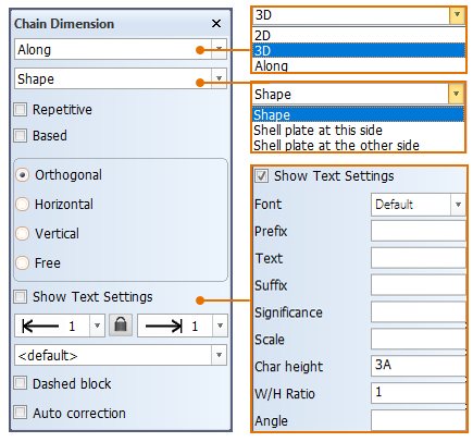
Dimension types
- 2D – Place 2D dimensions.
- 3D – Place 3D dimensions. The dimension is the shortest distance between the starting and end point. 3D dimensions can be placed in top, side, frame and perpendicular views.
- Along – Place dimensions along the hull shape or shell plates. The dimension is the distance between the starting and end point, measured along the hull shape or shell plates. These dimensions can be placed in top, side, frame and perpendicular views.
Projection options
Select how dimensions are projected on the drawing. These options are only available for 3D or Along dimension methods, and cannot be selected if the 2D dimension type is selected.
- Shape
- 3D – Shows the starting and end points of the dimension on the hull shape.
- Along – Shows the complete dimension along the hull shape
- Shell plate at this side
- 3D – Shows the starting and end points on the front side of the shell plate.
- Along – Shows the dimension on the front side of the shell plate.
- Shell plate at the other side
- 3D – Shows the starting and end points on the back side of the shell plate.
- Along – Shows the dimension on the back side of the shell plate.
Repetitive chain dimension
Place a series of consecutive, aligned dimensions.
Select Repetitive and do the following:
-
Indicate the starting point for the chain dimension.
-
Indicate the next point for the chain dimension.
You can also point to an item and press the space bar to indicate it. Use the snap keys to select a specific position on the item, such as the middle point (m). For more information, see Snap keys.
-
Indicate the position where you want to place the dimension.
-
Indicate the next item. Repeat step 4 as many times as necessary.
-
Press Esc to stop placing dimensions.
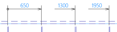
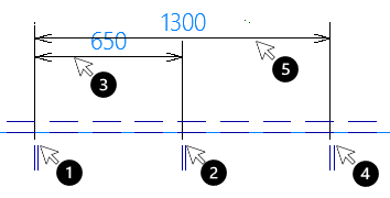
Based chain dimensions
Place a series of dimensions that have the same item as the starting point. The first indicated item is the base item from which the rest of the dimensions start.
Select Based and do the following:
-
Indicate the starting point for the chain dimension.
-
Indicate the next point for the chain dimension.
You can also place the dimension by typing in the distance from the first dimension:
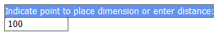
Positive values place the dimension in the outward direction, and negative values in the inward direction relative to the first dimension. The next dimensions are placed in the same direction using the same distance.
-
Indicate the position where you want to place the dimension.
-
Indicate the next item.
-
Place the dimension.
-
Repeat steps 3-5 as many times as necessary.
-
Press Esc to stop placing dimensions.
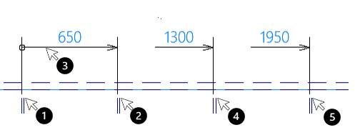
Repetitive based chain dimensions
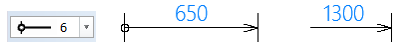
Place a series of consecutive, aligned dimensions that have the same item as the starting point. By default the starting point of the first arrow is circular (type 6) instead of the default one. This can be changed by selecting a new type from the arrow drop-down menu. The arrows following the first one are shortened slightly at their starting side.
Select Repetitive and Based and do the following:
-
Indicate the starting point for the chain dimension.
-
Indicate the next point for the chain dimension.
-
Indicate the position where you want to place the dimension.
-
Indicate the next item.
-
Indicate the next item, and repeat as many times as necessary.
-
Press Esc to stop placing dimensions.
Orientation
-
Orthogonal – Place dimensions that are perpendicular to the selected item.
-
Horizontal – Place horizontal dimensions.
-
Vertical – Place vertical dimensions.
-
Free – Place dimensions of any orientation. This way you can create diagonal dimensions, for example.
Text settings
You can define and use other than the default text property settings for the dimensions that you place. Select Show Text Settings to show and define these text settings. They are applied to the next dimensions that you place.
-
Font – The font used for the text
-
Prefix – Prefix to add to the dimension
-
Text – Text to add to the dimension
-
Sufffix – Suffix to add to the dimension
-
Significance – The number of decimal digits shown for the dimension length
Note: The Significance setting cannot be applied when imperial units are used, and therefore this setting is disabled for projects using the imperial unit system.
-
Scale – Scale used for the dimension. Only available for chain dimensions.
-
Char height – The character height of the text
-
W/H Ratio – The width-to-height ratio of the text
-
Angle – The angle of the dimension text
Tip: Prefixes and suffixes can be used for distiguishing between breadth and length values, for example.
Arrow types
You can select the begin and end arrow types for the dimensions.
The default arrow is defined in Tools > Settings > More Settings Functions > Block Properties, in the Text Properties tab, Dimension settings group.
Selection filter
A selection filter defines which type of items can be selected in the graphical window. You can filter the items by selection group or by individual item type. The available individual item types depend on the active Hull application.
Selection groups appear at the top of the list. A selection group contains those item types that the Hull System Administrator has included in it. Selection groups are defined in the System Management application, Extra > Customize > Dimensioning > Default Selection Groups.
Dashed block
Select Dashed block to make also dashed items selectable.
Auto correction
When Auto correction is selected, the system snaps the measurement point to the nearest end of the selected item at the molded side, and adds thickness direction indications.
When Auto correction is not selected, the exact point on the item indicated is used as the measurement point, and thickness direction indications are not shown.