Symbols
Draw > Symbols
Add symbols to the drawing. Select from the following options:
Part Labeling – Position, replace, or move part numbers and part dimensions for construction items. See Part Labeling below for details.
Profile Size Series – Add a series of profile size symbols to the drawing.
Profile Symbol – Add profile symbols to the drawing.
Plate Thickness in Section – Add a shell plate thickness in section symbol to the drawing.
Hole Symbol at Line – Add hole symbols to lines. Indicate a point on a line. Enter the hole size and the breadth, and click OK.
Face Plate Endtype Symbol – Indicate flange/face plate at the side where to place the symbol.
Weld Dimension – Add weld dimensions to the drawing.
Detail Indication – Indicate the centre point for the symbol position. Enter the detail number, and click OK.
Section Symbol – Add a section symbol to the drawing.
Reversed Frame – Indicate the centre point for the symbol position.
Centre Line of Circle – Draw a vertical and horizontal center line. Indicate a circle/arc where to draw the line.
Centre Line Symbol – Add a centre line symbol to the drawing. The centre line symbol is placed scale-depended (the symbol will be enlarged with a factor scale/25). However, once the centre line symbol has been placed, it will not be re-scaled when the scale of the drawing is changed.
Modification Arrow – Add a modification arrow symbol to the drawing.
Modification Cloud – Add a modification cloud symbol to the drawing.
Joggle – Indicate a weld symbol to be joggled.
Part Labeling
Place or move part labels for the following construction items:
- plates
- shell plates
- brackets
- shell frames
- profiles
- face plates
- flanges
- lugs (collar plates)
- (outfitting) equipment
- database parts
When activated in the System Management application, it is also possible to simultaneously enter or modify logistical data of the item to be labeled.
- Related setting in the System Management application: Logistics During Part Labeling.
See also Placing part labels.
Use the Function dependent options to set the part label type (dimension, text or number) to be placed.
The hint reflects the current selection method, and part label types for plates and profiles and other items.
- Dimension – Sets the part label type to be placed to Dimension. This option will be replaced by Text. FDO 6 is for plates, and FDO 7 for profiles.
- Text – Sets the part label type to be placed to Text. This option will be replaced by Number. FDO 6 is for plates, and FDO 7 for profiles.
- Number – Sets the part label type to be placed to Number. This option will be replaced by Dimension. FDO 6 is for plates, and FDO 7 for profiles.
- Line selection – Sets the selection method to Line selection. The hint is changed into "Select item by Line selection .../...". This option is only available when the part label type for profiles has been set to either Text or Number.
- Box selection – Sets the selection method to Box selection. The hint is changed into "Select item by Box selection .../...". This option is only available when the part label type for profiles has been set to either Text or Number.
The following keyboard shortcuts can be used to position the part label:
-
f – Places a part label, or repositions an existing part label, to the indicated point. Forces the position to this point and revents the system from selecting the nearest part. Normally when placing a part label, the system attempts to select the part nearest to the indication point, which could lead to replacement of the part number attribute of an existing part.
-
c – Select a part in cross-section.
-
p – Creates a new part number attribute and removes the existing part number attribute if one exists.
Important: It is not recommended to use this keyboard shortcut to reposition a part label, because doing so will remove the existing part number attribute from the logistical data and create a new one. This could change the position of the part in the WBD tree. Use a keyboard shortcut for the relevant Function Dependent Option (FDO) instead to move part labels. See Moving part labels.
Select item by point, place ../..
Click with the left mouse button as close as possible to the construction item to be labeled.
- Use the keyboard shortcut f to force the position to a point. This is useful in situations where other item types are close to the position of the part that you want to select.
- Use the keyboard shortcut c when you need to label a construction item type in cross section that is not included in the default "selectable construction items in section" list, set by the Hull Administrator.
You can also select an already existing part label and move it to another position. Select the part label, and drag it to the desired new position.
- By default, if a part number attribute already exists for a plate, the attribute is kept and moved to the indicated position without placing a new part number. You can override the default behavior by using the keyboard shortcut p. A new part number attribute is placed for the plate in this case. The old part number attribute will be removed when the drawing is next updated. It is advisable to use this method as little as possible, because manually added part information will be lost, and also the part will be moved to the top level in the work breakdown structure.
When a plate contains soft seams or splitters, the system must create extra part number attributes. They are indicated by a blue cross.
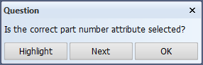
When adding a new part label, the system finds and selects the part number attribute nearest to the cursor position. You can use the information of the selected attribute for the new label, or you can select another attribute whose information to use. The system displays a confirmation dialog where you can make your choice:
-
Highlight – Highlight the part number attribute that is currently selected.
-
Next – Do not use the information of the selected part number attribute. The system finds and selects the next part number attribute that belongs to the same plate. The confirmation dialog is displayed again.
Note: The confirmation dialog is not shown when the next part number attribute would be the last one. The information of the last part number attribute is used without asking confirmation. This means that if there are just two part number attributes, and you reject using the first one by clicking Next, the system will use the second part number attribute without asking for confirmation.
- OK – Use the information of the selected part number attribute for the new label.
Select item by line selection, place .../...
- Indicate the starting point of the (temporary) line either by clicking with the left mouse button or by using the keyboard shortcut f.
- Indicate the ending point of the line either by clicking with the left mouse button or by entering the length and angle of the line with respect to the starting point.
All profiles which are intersected by the (temporary) line will get a part label at their intersection point with the line. No part labels for other intersected construction items will be placed.
Note: The Line selection method can only be activated in the Point selection mode when the part label type for profiles has been set to either Text or Number. Part labels for plates can not be placed in the Line selection mode.
Select item by box selection, place .../...
- Indicate the starting point of the (temporary) line either by clicking with the left mouse button or by using the keyboard shortcut f.
- Indicate the ending point of the line either by clicking with the left mouse button or by entering the length and angle of the line with respect to the starting point.
All profiles which are intersected by the (temporary) line will get a part label at their intersection point with the line. No part labels for other intersected construction items will be placed.
Note: The Box selection method can only be activated in the Line selection mode when the part label type for profiles has been set to either Text or Number. Part labels for plates can not be placed in the Box selection mode.