Knuckles
Production > Plate Cutting Data > Knuckles
The knuckles settings are organized into the following setting groups:
Introduction to the knuckles settings
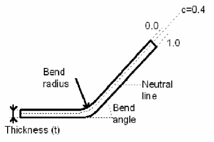
When bending a plate, the plate becomes shorter along the inner side of the bent plate and longer along the outer side. For coding it is important to know how much this extension has to be, so that the plate has the desired dimensions after bending. For this purpose, the concept of neutral line exists. Neutral line is the position in the plate where the length does not change while bending:
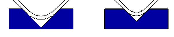
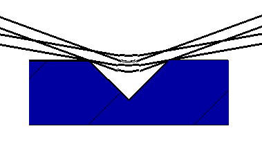
In addition to this, the bend radius is important, because the bend radius together with the distance from the neutral line to the inside of the plate will yield the exact length of the bent plate. The bend radius depends on the mould opening that is used for pressing the plate into the correct position. A wider mould opening results in a larger bend radius, as shown in the image below.
Determining the neutral line and plate length
To determine the neutral line and the plate length, three tables are used. The tables are composed by entering some values manually in the some of the settings in the Knuckles > Settings dialog. Some values are then calculated by the system based on the manually entered values. See below.
When a knuckle or flange is calculated, the bend radius and mould opening are determined first. These depend on the plate thickness, as shown in the table below. The bend radius and mould opening are specified with the Knuckles > Settings > Configuration Table setting (Inner rad. and Mould open., respectively).
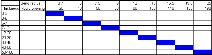
The table is fairly exact for 90 degree knuckles, but for a larger degree knuckles it is an estimation. With larger that 90 degree knuckles the mould opening, together with the angle, is more important than the radius. That is why the radius changes when the knuckle angle is different. See the example below.
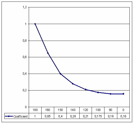
Therefore, for bend angles other than 90E the bend radius is determined based on another table, which is defined with the Knuckles > Settings > Bending Radius setting where you specify a Knuckle angle and a Coefficient. As the table below shows, a coefficient is calculated depending of the inside bend angle. The resulting coefficient multiplied with the specified mould opening will be the used bend radius.
Coefficient = depends on the inside bend angle
Bend radius = coefficient X mould opening
Then, knowing the bend angle, plate thickness, end radius, and mould opening, the position of the neutral line can be determined by using the third table. This table is defined with the Knuckles > Settings > Bending, Neutral Line setting, where you specify Thickness factor and Correction factor.
The position of the neutral line (correction factor 0#c#1) is influenced by the thickness of the plate and the bending radius. If the factor c is 1, the neutral line is calculated at the half thickness of the plate. If the factor c is 0, the neutral line will be positioned on the inside of the plate. In that case only the bending radius will be used.
The c factor you specify will be used as shown in the table below. The position c of the neutral line can be set for several bending radii. The bending radius is expressed as a factor times the thickness. This factor is called the thickness factor.
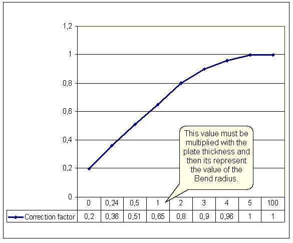
If the value (0 - 0,24 - 0,5 - 1 - 2 - 3 - 4 - 5 - 100) multiplied with the plate thickness correspond with the bend radius, the correction factor is defined. The correction factor multiplied with the half plate thickness present the neutral line distance from the inside of the plate.
Example
If the plate thickness is 20mm and the bend radius is 60mm, the c factor will be 0.9. which means that the neutral line will be 9mm from the inside of the plate. The radius used for the calculation of the correct plate length will be 69mm in this case. The arc length will be used as the exact length. In this case the c factor is 0.9 because 20 multiplied by 3 is 60, and as the table shows, value 3 will yield factor 0.9.
Distance from a knuckle line to the plate contour
It is possible to incorporate the distance from a knuckle line (knuckles and flanges) to the contour in the DXF file of a coded part. This concerns the distance perpendicular to the middle of the knuckle line up to the contour.
One of two distances can be used for this purpose. Which one will be used depends on whether the contour is parallel to the knuckle line or not, and two settings:
The shortest distance is used, unless the measured distance to a parallel contour line is longer than the user defined maximum. This is set in Knuckles > Dimensions > Max. Dist. To Parallel Contour. Also, the distance must be greater than a user-defined minimum, set in Knuckles > Dimensions > Minimum Distance To Contour, or no dimension will be added.
The dimension is placed along a line segment with a user-defined length. This is set in Knuckles > Dimensions > Length Line (Contour Distance). You can add a prefix and a postfix to the dimension. These are defined with Knuckles > Dimensions > Prefix For Contour Distance and Postfix For Contour Distance, respectively.
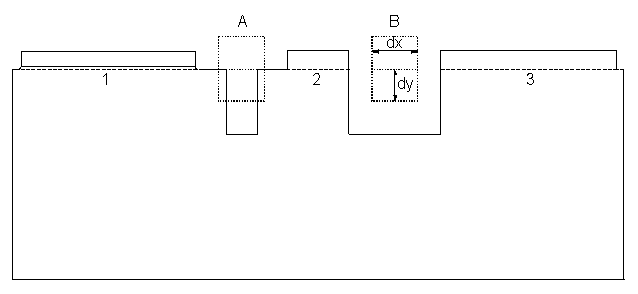
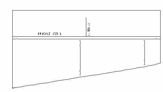
It is possible that several knuckle lines are positioned on the same (imaginary) line (see the illustration below). The calculated length can then equal the sum of two or more knuckle lines. This depends on a setting with which a rectangle can be defined, Knuckles > Settings > Rectangle Total Knuckle Length. If the rectangle fits between two knuckle lines, the knuckle lines are regarded as separate (B). If the rectangle does not fit, the greatest length between the ends will be taken as the length (A). Finally, the length of the longest knuckle line will be stored. In the example below this is therefore the distance between the left side of line segment 1 and the right side of line segment 2.