Creating arbitrary profiles
To create an arbitrary profile, select Construction > Profiles > Insert > Arbitrary in the 3D-Contek application. The Create Profile dialog opens.
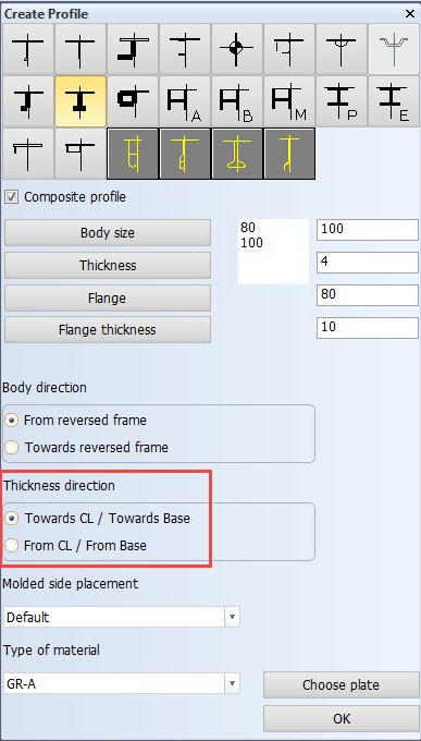
This dialog is for defining the type of profile, the body and thickness direction. Because it is not known whether the profile will be horizontal or vertical at this point, the Thickness direction selection is ambiguous. The plate on which the profile is to be created can be indicated in the graphical window once Choose plate is clicked.
For more detailed information on the selections available here, see Creating horizontal and vertical Profiles.
Click OK to approve the settings. A dialog where you define the relations of the profile opens:
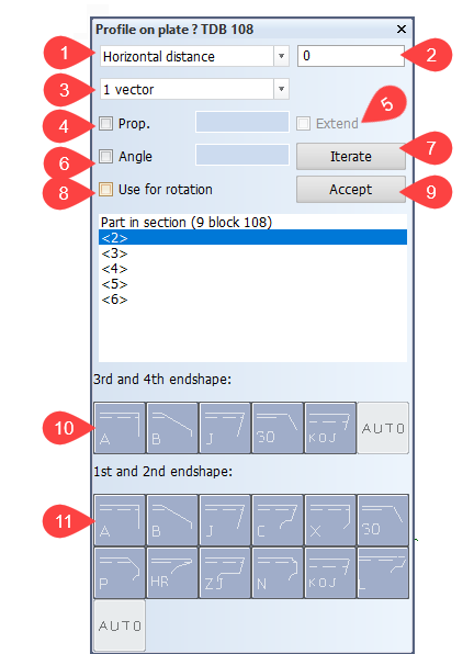
-
Set the distance of the profile to certain relations here. The following distances are available in the drop-down menu:
- Horizontal distance
- Vertical distance
- Parallel distance
- Axial distance
- Fixed length
- Fixed width
-
Specify the length of the distance that was defined in drop-down menu (1). If you selected a fixed value for the distance, add the value here.
-
Select the type of the relation:
- Complete relation – the entire relation
- 1 vector – a vector of the relation that is closest to the indicated point
- Box – the smallest rectangle around the relation
- Minimal – point of the relation that is closest to the other end of the profile
- Point – point of the relation that is closest to the indicated point
-
Select Prop. (proportional) to have the profile end described by three relations. Select this before defining the 1st partial relation. In the input box on the right, define the part of the contour length, or the length of the line through intersections A and B, on which the profile and is to be placed. Add the value before defining the 1st partial relation. The value must be between 0.0 and 1.0.
-
Select Extend to extended the profile toward the third relation. In this case, the distance on the 3rd partial relation will be measured along the straight line through the intersections of the 1st and the 3rd and the 2nd and the 3rd relation, instead of measuring it along the contour between these points.
-
Select Angle to have the current relation intersected under an angle from the previous profile end. Define the used angle in the input box on the right.
-
Select Iterate to repeat the profiles created. Enter how many times the profile should be repeated, and click OK. The Iterate dialog opens. Here you define the distribution of the profiles. Here you define the distribution of the profiles. See Example on using the Iterate option below.
-
Select Use for rotation to have the system use the relation that has been indicated last to rotate the profile. See Related profile angle for more information.
-
Once you have defined the relation, click Accept to create it. The created relations are shown in the box in the middle of the dialog.
The created relations are also modifiable. For example, the distance of a selected relation can be modified or removed by selecting it in the list of relations. You can also completely replace a relation by another one.
If you click an already accepted relation, you can modify, remove or replace it while adding a new relation.
-
Available 3rd and 2nd endshapes.
-
Available 1st and 2nd endshapes.
Example on using the Iterate option
Clicking Iterate (7) opens a dialog for entering the number of iterations.
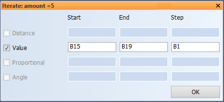
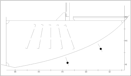
In this example we create a series of five profiles. The first profile should be positioned at width B15, the last profile should be positioned at width B19. The first limitation of these profiles is on a height of H9+100, the other end should be related to a plate in section with a parallel distance of 100 mm and under an angle from the base that varies between 70 and 110 degrees. To create these profiles, do the following:
- Choose a fixed height, and enter H9+100 as the value.
- Choose a fixed width, and enter B15 as the value.
- Click Iterate, and enter 5 for the amount.
- Enter B19 for the end value (1B will appear as step size)
- Select the plate in section.
- Click Angle, and enter 70 as the angle value.
- Click Iterate, and enter 110 as end value (10 will appear as step size).
The image below shows the desired end result:
You can find another example on how to use arbitrary profiles in chapter Deck 3500 Above Base – Part 2 of the Structural Design User Training Tutorial in the Help.