Creating horizontal and vertical Profiles
To create a horizontal or a vertical profile, select Construction > Profiles > Insert > Horizontal or Vertical in the 3D-Contek application. The Create Horizontal Profile or Create Vertical Profile dialog opens.
Note: The terms "horizontal" and "vertical" do not refer to the actual position of the profile within the ship, but to the position of the profile as it is presented in the drawing.
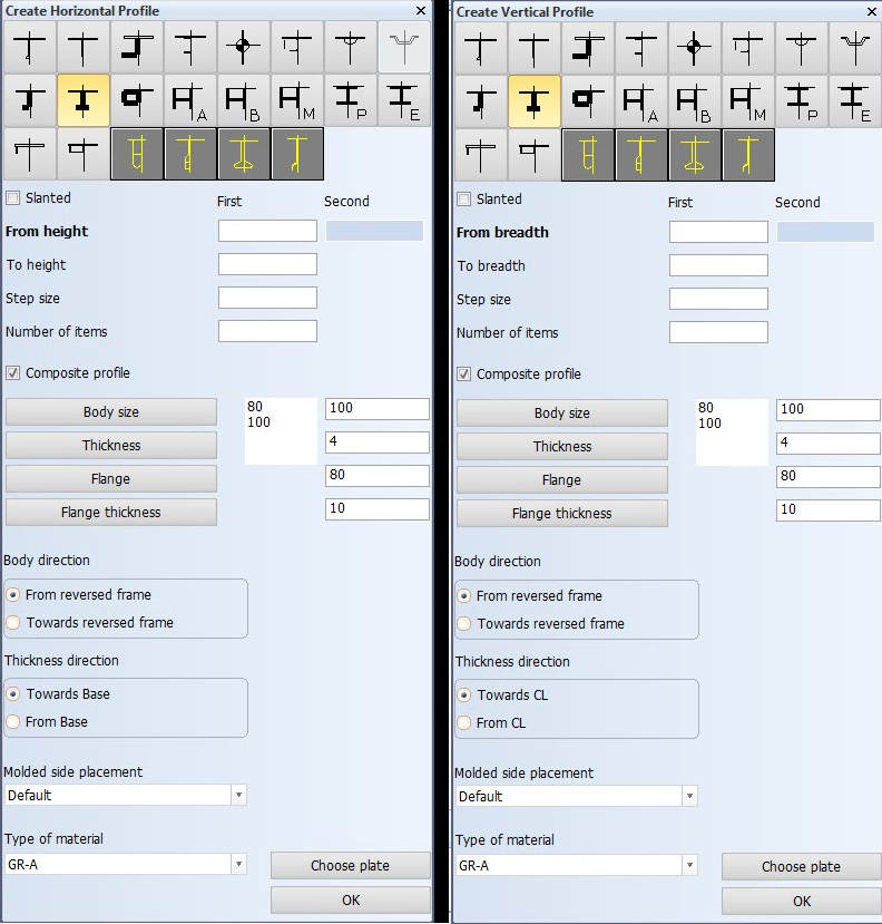
Define the following:
-
Profile types – Select the type of profile to insert. The thumbnails show the structure of each available profile.
-
Slanted – Create a slated profile. Define a second width/length/height for the slanted profile. The first value will be combined with the first limitation (relation), and the second value will be combined with the second limitation. Note that a series of profiles will be parallel only if both indicated limitations combined with the fixed values that are entered, are parallel and straight.
-
Fixed values – Horizontal or vertical profiles always have four relations: two fixed values and two user defined relations. You can click the frame numbers or grid lines in the drawing to define the fixed values. Click with the left mouse button to set the start value, and the right mouse button to define the end value.
-
Step size – The distance between the profiles. If left empty, the system applies an equal distance between the start and end profiles.
-
Number of items – The number of profiles to be placed. If left empty, the system determines the number of profiles based on the other entered values.
-
Composite profile – You can code bodies and flanges for certain profile types separately, while the design system still treats the profile as one complete construction item. These profiles are called composite profiles. For more information, see Composite profiles.
-
Body size and Thickness – Set the size and thickness for the body of the profile.
-
Flange and Flange Thickness– Set the size and thickness for the flange of the profile.
-
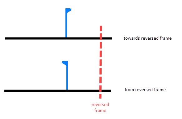
Body direction – Define the orientation of the body. The orientation can be either from or towards the reversed frame.
-
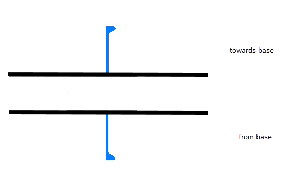
Thickness direction – Set the thickness direction of the profile. The thickness direction can be either towards or from the base (horizontal profiles), or towards or from the center line (vertical profiles).
-
Molded side placement – This setting sets the molded side of the profile. By default a profile is placed by its molded side. It is possible that the profile is not aligned as desired with the construction item that is located on the other side of the plate, if both parts have the default thickness direction. This is because it is the molded lines of the parts that are aligned. By changing the molded side placement it is possible to change how the profile is aligned with the construction item that is located on the other side of the plate. The molded side position can be changed from the default to the midpoint of the profile body, or to the thickness side of the profile.
 Show/hide image
The image below shows the three available options:
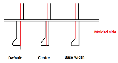
See Molded side placement for profiles for more information.
-
Type of material – Select the material type of the profile.
-
Choose Plate – Select the plate where the profile is placed on in the graphical window. If no plate is indicated, the system will choose one. This will take some time, and indicating a plate might be faster. If the calculated position of the profile is on another plate than the indicated one, it will be attached to this plate. If the calculated middle of the profile is not on any plate, the profile will not be created, and you will need to indicate a plate.
Click OK. The Border value dialog opens.
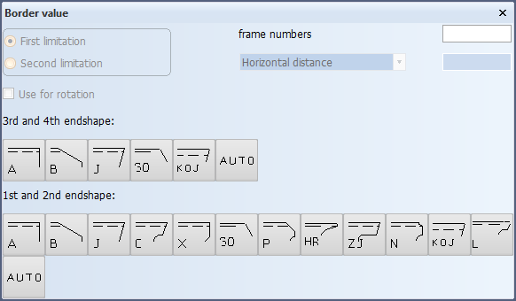
Define the first limitation of the profile by indicating a construction item, hull line, yellow menu line, or enter fixed values.
Confirm the limitation by clicking the desired 1st or 2nd endshape. If the 3rd or 4th endshape is not selected, a default (defined in label 6 of the type macro) will be used. If a 3rd or 4th endshape is selected, the 1st or 2nd endshapes that are not allowed are unavailable (this is defined in label 6 of the type macro).
After selecting the limitations, the profile appears in the graphical window.
Bent profile on plate as a limitation
It is possible to select a bent profile in view as a limitation for the profiles.
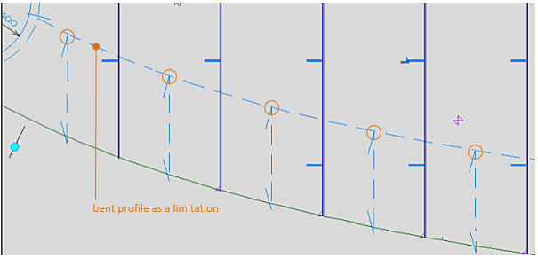
To ensure that the profile end relations are correct, that is, that the profiles are created along the curved contour of the bent profile, the system uses Complete relation as the default relation property.
A different relation property can be selected when indicating the bent profile as a relation: right-click the bent profile, and select the desired relation property from the context menu that opens.
See Relation properties for more information.