Arbitrary pillars
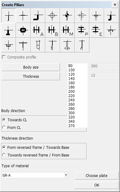
To create an arbitrary profile, select Construction > Pillars > Insert > Arbitrary in the 3D-Contek application. The Create Profile dialog opens.
Define the following:
-
Pillar types – Select the type of pillar to insert. The thumbnails show the structure of each available pillar.
-
Composite profile – You can code bodies and flanges for certain pillar types separately, while the design system still treats the pillar as one complete construction item. These pillars are called composite profiles/pillars. For more information, see Composite profiles.
-
Body size and Thickness – Set the size and thickness for the body of the pillar. For composite pillars, the flange size and thickness are set in the input boxes on the right.
-
Body direction – Define the orientation of the body. The orientation can be either from or towards the reversed frame.
-
Thickness direction – Set the thickness direction of the pillar. Because it is not known whether the profile will be horizontal or vertical at this point, this selection is ambiguous.
-
Fixed values – Horizontal or vertical pillars always have four relations: two fixed values and two user defined relations. You can click the frame numbers or grid lines in the drawing to define the fixed values. Click with the left mouse button to set the start value, and the right mouse button to define the end value.
-
Type of material – Select the material type of the pillar.
-
Choose Plate – Select the plate where the pillar is placed on in the graphical window. If no plate is indicated, the system will choose one. This will take some time, and indicating a plate might be faster. If the calculated position of the pillar is on another plate than the indicated one, it will be attached to this plate. If the calculated middle of the pillar is not on any plate, the illar will not be created, and you must indicate a plate.
Click OK. In the dialog that opens you define the relations of the pillar.
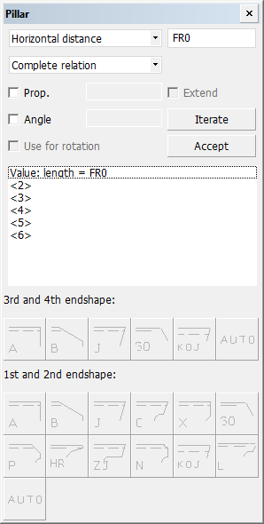
Do the following:
-
Set the distance of the pillar to certain relations here. The following distances are available in the topmost drop-down menu:
- Horizontal distance
- Vertical distance
- Parallel distance
- Axial distance
- Fixed length
- Fixed width
-
Specify the length of the distance in the input box on the right.
-
Select the type of the relation:
- Complete relation – the entire relation
- 1 vector – a vector of the relation that is closest to the indicated point
- Box – the smallest rectangle around the relation
- Minimal – point of the relation that is closest to the other end of the pillar
- Point – point of the relation that is closest to the indicated point
-
Select Prop. (proportional) to have the pillar end described by three relations. Select this before defining the 1st partial relation. In the input box on the right, define the part of the contour length, or the length of the line through intersections A and B, on which the pillar and is to be placed. Add the value before defining the 1st partial relation. The value must be between 0.0 and 1.0.
-
Select Extend to extended the pillar toward the third relation. In this case, the distance on the 3rd partial relation will be measured along the straight line through the intersections of the 1st and the 3rd and the 2nd and the 3rd relation, instead of measuring it along the contour between these points.
-
Select Angle to have the current relation intersected under an angle from the previous profile end. Define the used angle in the input box on the right.
-
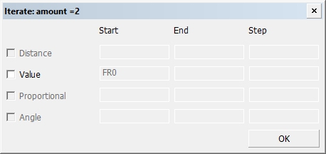
Select Iterate to repeat the pillars created. Enter how many times the pillar should be repeated, and click OK. The Iterate dialog opens. Here you define the distribution of the pillars. See Example on using the Iterate option.
-
Select Use for rotation to have the system use the relation that has been indicated last to rotate the pillar. See Related profile angle for more information.
-
Once you have defined the relation, click Accept to create it. The created relations are shown in the box in the middle of the dialog.
-
Select the endshapes if necessary.