File structure of Hull Line Properties
The HLProperties file follows the basic structure of the XML specification, including headers for encoding and the DTD (document type definition).
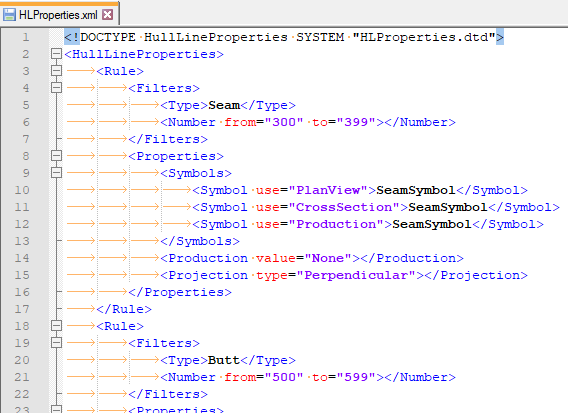
The root element is <HullLineProperties>, and all of its children are <Rule> elements.
Each Rule contains an optional <Filters> child element and a <Properties> child element, which contain the actual data that define the rule and the properties of your hull lines.
Filters
Each <Filters> element contains at maximum one of each of the following elements:
- <Source>
- <Type>
- <Number>
Source – Use the <Source> element to define the database where the hull lines are located at. Allowed values are Hull, Other, and All. Hull refers to the hull line database (HL-DB) of lines that were created in CADMATIC Hull, while Other refers to all other lines (for example those that are defined in the shape database). All includes both hull lines created in CADMATIC Hull and in other shape databases.
Type – Use this element to define the type of the hull lines you want to filter to. The system allows a set of criteria for hull line type. There are multiple ways to refer to the same line type; for example, seams might be referred to as SE or Seam. The system supports the all full names and known abbreviations listed below as line types.
Table below contains all the names and abbreviations The values are case-sensitive.
| Name | Abbreviation |
|---|---|
| AngledCurve | AL |
| FunctionLine | FL |
| Knuckle | KN |
| DsLine | DS |
| Sent | ST |
| Frame | FR |
| Vertical | VK |
| WaterLine | WL |
| Butt | BU |
| Seam | SE |
| LineInPlane | LN |
| AuxiliaryLine | AX |
Number – Specify with from and to attributes a range. If no from attribute is defined, the minimum value 0 (zero) is used. If no to attribute is defined, the maximum value 100.000 is used. These values are inclusive (i.e. the edges belong to the range), must be integral, and have a minimum value of 0 (zero) and a maximum value of 100.00 for line numbers (these values are based on the respective limits for the actual values).
Properties
Each Properties element contains the following elements:
- <Symbols>
- <Production>
- <Projection>
Symbol – A group of 3 Symbol elements. It contains at least 3 elements: PlanView, CrossSection and Production are compulsory. The attribute use must be set to one of the following values: PlanView, CrossSection, Production. The xml node content is the file name of the symbol. If the file name does not contain a file extension, it is automatically added by the system depending on the use attribute.
See Symbol for more information on how to use the Symbol properties.
Production – The value attribute must be set to one of the allowed values.
See Production property for more information on the available values and their purposes.
Projection – The type attribute must be set to one of the allowed values.
see Projection method for more information on the available types and their purposes.
Topic Examples provides you with some examples on correct and incorrect rules.