Elongation and shell plate bending overview
Curved and double curved shell plates need to be bent to their final shape. Elongation is used when deforming a flat plate to its final 3D shape. The bending process deforms the shell plate by changing its shape and size. Elongation compensates the deformation that the bending process causes.
A spherical plate gets its highest elongation in the middle section of the part, and a saddle-shaped plate gets the highest elongation at the sides. If the shell plate is completely flat, a cone, or a cylinder, it is not necessary to add elongation.
How the plate size changes depends on the material of the shall plate as well as the bending process:
-
For Cold bending elongation is used to enlarge the plate.
-
For Line heating elongation is used to shrink the plate.
Based on the elongation the plate will be cut bigger in case of line heating and smaller in case of cold forming.
For both line heating and cold forming bending methods elongation is always expressed as a positive value.
The elongations for each shell plate are presented in Shell plate elongation reports, which are based on a customizable Elongation report template. The system creates the elongation reports when shell plates are coded.
Calculation and presentation of elongation
The system calculates the elongation in each mesh of a shell plate.
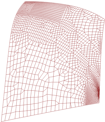
Shell plate meshing. Each rectangle/triangle is considered a mesh.
The calculated elongations are shown in elongations reports, which are generated for each coded shell plate. The amount of elongation is presented as a color map and in labels on top of the shell plate image. Each label contains a numerical elongation value, and the colors in the color map each represent a certain elongation value.
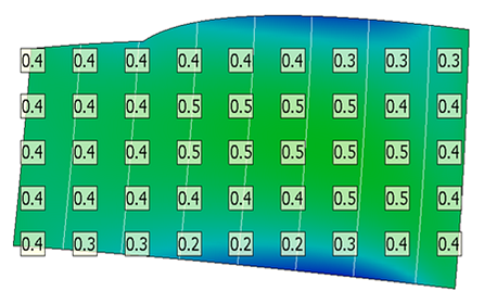
Color map and labels on shell plate image showing the amount of elongation
Note: Elongation can also presented as an elongation table which shows the elongation values for each of the shell plate's template, at defined points of the templates. See Elongation table for more information.
The labels on the shell plate image are placed on a grid. The grid can be defined in System Management > Production > Shell Plates Elongation List > Settings with the Color Map Label Horizontal Spacing and Color Map Label Vertical Spacing settings. These settings define the horizontal and vertical points in the grid. The labels are placed at the intersection points (nodes) of the horizontal and vertical grid points, and they show the elongation per square meter at each intersection point.
The elongation values in the labels are calculated as follows:
<elongation value of the mesh> x <elongation factor>
The elongation factor is a multiplication factor that is applied to the strain values. It determines how the elongation value is expressed. The elongation factor is set in System Management > Production > Shell Plates Elongation List > Settings > Elongation Factor. The default value is 1000, which will convert the strain values, and set the presentation of elongation, to mm/meter.
The colors used in the color map are defined in System Management > Production > Shell Plates Elongation List > Color Map – Color Rules.
Interpreting the values and colors
A shell plate shape often has variations in curvature. While the elongation is shown in the labels at grid positions, the color map shows the elongation between the grid positions. The colors show how the elongation values are distributed between the grid positions (labels).
Typically the elongation does not have much variation between the grid positions, especially when there is not much curvature in the shape. The curvature variation mostly stays within practical limits in the case of normal curved shell plate.
When the elongation changes within a grid length (horizontally or vertically), the elongation should be used for only the length of the plate with the same elongation.
It is recommended to align the elongation factor and grid length according to the deformation method used on the workshop floor. A practical grid length is often the average frame distance. The elongation value itself can be used to define the bend pressure of the bending machine by cold forming.
Also note that in the shell plate images the elongation is expressed in all directions, not only in the length direction of the shell plates. This is especially important to notice when the shell plate is more square than rectangular.
Shell plate bending process
The bending process is mostly done by human workforce and requires professional skills. The insight of this personnel is very important for achieving a good result and for reducing the time spent on the bending process to minimum. Choosing the wrong bending process can result in wasting the plate. Production personnel use templates generated by the Hull engineers to understand the curvature and torsion of the plate. The templates also help them to find the cylindrical or conical directions. In some cases the roller line can help, but the bending process to achieve the 3D curved shape is mainly a handicraft process.
The boundaries of the shell plate are created by the Hull engineer. The system does not limit the size or the shape of the shell plate. The engineer can create basically any kind of shapes, but the production personnel must consider many limitations, such as the plate size and material, the type of the bending tool, or even the size of the production area.
The elongation grows significantly when the width of the shell plate is increased, and more skill is required to handle the higher elongations. The production personnel should inform the Hull administrator what are the maximum elongation values they can handle. The Hull administrator can then set the minimum and maximum limits for elongation. See Extremity rules for elongation reports for more information on the minimum and maximum elongation values. The material type and thickness of the plate also affect the limits of the acceptable deformation.
The Hull engineer should always consider the limitations indicated by production when designing the shell plates. When the elongation has exceeded the maximum values, the Hull engineer should double-check if the boundaries and the shape of the shell plate are correct. Shell plates with shorter width are usually easier to handle.
The elongation report helps to control the results. Plates with high elongations values should be checked, and possibly considered as unacceptable for production.