Adding a single bevel
The Construction > Bevels > Insert > Single Bevel function is used to define a bevel for one particular edge of a part or between two parts. This function is similar to the Bevels function which is used to place multiple bevels in one go.
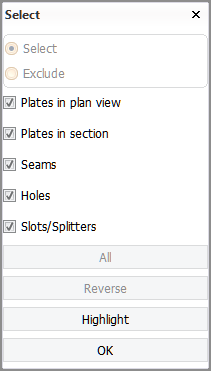
When you start the function, the Select dialog opens. The options in this dialog enable you to select certain types of parts in the graphical window: a plate or two plates, a seam, hole or slot/splitter.
In case of a plate split by seams (panel), select the desired plate part. Bevels are placed onthe edges of the plate part, not on the entire edge of the panel.
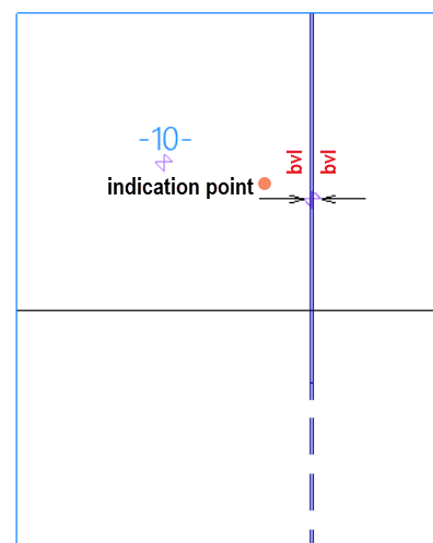
In a situation where a vertical slot/splitter spans across two plate parts which are separated by a horizontal seam, the placement of the bevel depends on the indication point.
-
To place the bevel on a plate part located above horizontal the seam, indicate right above the slot/splitter arrow.
-
To place the bevel on a plate part located below the horizontal seam, indicate right below the slot/splitter arrow.
You can also use a clump or conflict selection. The center of the clump/conflict box must be on the desired plate part, and the slot/splitter must belong to the selection. See Indicating items for information on the clump/conflict selection.
 Show/hide image
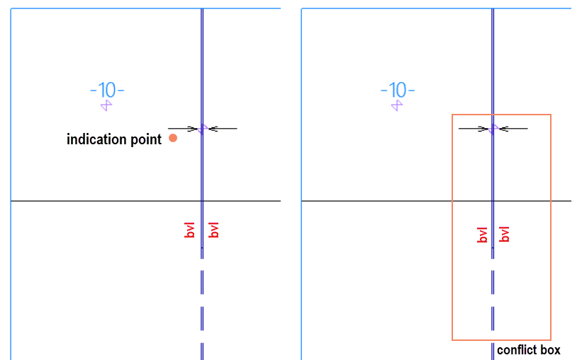
Left: Selection by indication point
Right: Selection by conflict box
Note: If significant modifications are made to the seams splitting the panel, or if the seams are modified several times, manually added bevels on the seams or on the edges of the plate parts might disappear. In some cases, the system might substitute these manually created bevels with automatically generated ones. See also Note on manual bevels on a split plate edge.
Once you have selected the desired part or two parts in the graphical window, click OK. Selecting more than two parts will trigger a warning.
The properties of the bevel are defined in the Bevels dialog. See Bevel properties for predefined bevels for detailed information.
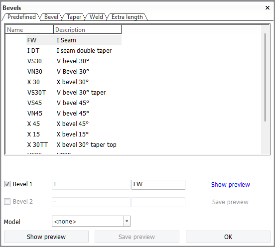
The system will automatically begin with the predefined bevel which matches the rules defined by the system administrator in the Bevel configuration files. In the Predefined tab you can select which type of predefined bevel should be placed.
The other four tabs are used for changing the properties of the bevel
-
Bevel – The type, angle and other properties of the bevel. See Bevel tab.
-
Taper – The tapering properties of the bevel. See Taper tab.
-
Weld – The weld connection and shringage compensation settings of the bevel. See Weld tab.
-
Extra length – Set the size of extra length on the plate edge. See Extra length tab.
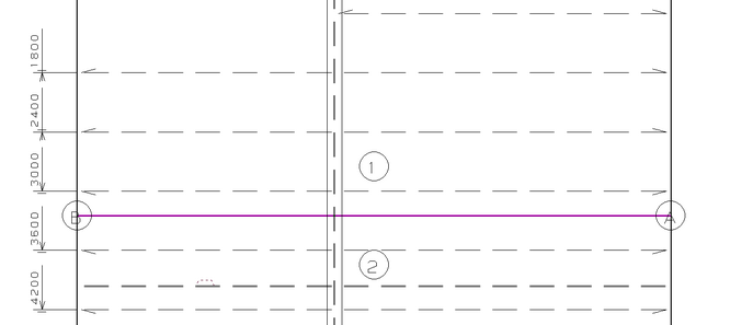
While the Bevels dialog is open, a magenta colored line is shown in the graphical window along the location where the bevel would be placed. The two involved parts are labeled 1 and 2. The bevel line is marked by A at the start, and B at the end.
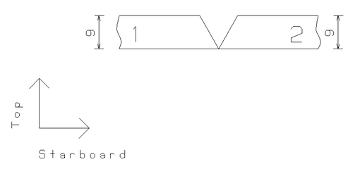
Clicking Show preview in the Bevels dialog generates a view in the graphical window of what the shape of the parts will be after the bevels are applied. Numbers 1 and 2 show to which part each shape in the preview belongs to.
The bevels can also be switched on or off using the Bevel 1 and Bevel 2 selections in the Bevels dialog.