Weld symbols
Weld symbols can be applied to seams with the Construction > Welds > Symbols/Dimensions > Symbols function. This function allows a symbol representing a weld to be manually placed at a seam.
Existing weld symbols can also be replaced in a similar fashion by using the function Construction > Welds > Symbols/Dimensions > Replace Weld Symbols.
The weld symbols available for drawings must be specified in System Management > Tools > Modify Icons > 3D Contek. See Customizing weld symbols for more information on modifying weld symbols.
Weld line end symbols
Weld line symbols are presented automatically in the 2D-Contek, 3D-Contek, Production Information, and Shell applications when the Presenting weld lines option is selected in the drawing properties. The symbols are presented at both the start and end points of a weld line, as long as the weld line is greater than or equal to the value defined in the Minimum Line Length for Symbols Presentation setting in System Management > Presentation > Weld Lines.
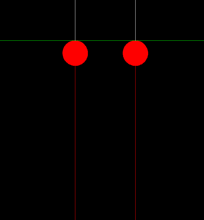
Default weld line end symbols applied to two weld lines
The model used as the weld line end symbol uses the same fragment number and attribute information as the weld line. The size of the model is scaled to 1:25 by default, but changes proportionally to changes to the drawing scale. The model used for the weld line end symbol must be called weldend.mod, and it should be placed in the models directory within the active norms. This location of which is set in System Management > Projects > Properties > Models Directory. If the model is customized by the system administrator, the new model must be symmetric around the y-axis and begin at x=0, since the weld line end symbol does not extend past the end of the weld line. The arrangement of the default symbol can be seen in the example below.
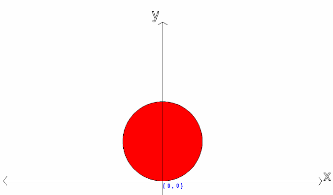
The weld line is displayed over top of the weld line end symbol, so the weld line will display continuously between the end points.