Bolts, nuts, and washers
Bolt Sets can include bolts, nuts, and washers of various sizes. Their dimensions must be defined in dimension tables, while their other properties (such as standards and materials) are defined in catalog parts.
To include joint materials in Plant Modeller sessions and generated reports, bolt sets must be assigned to the relevant connection types in the piping specifications.
To visualize joint materials in the 3D model, bolt sets must be assigned to the correct pressure rating and face sub-type in the 'Bolt information' configuration, and the related catalog parts must have the appropriate joint material attributes.
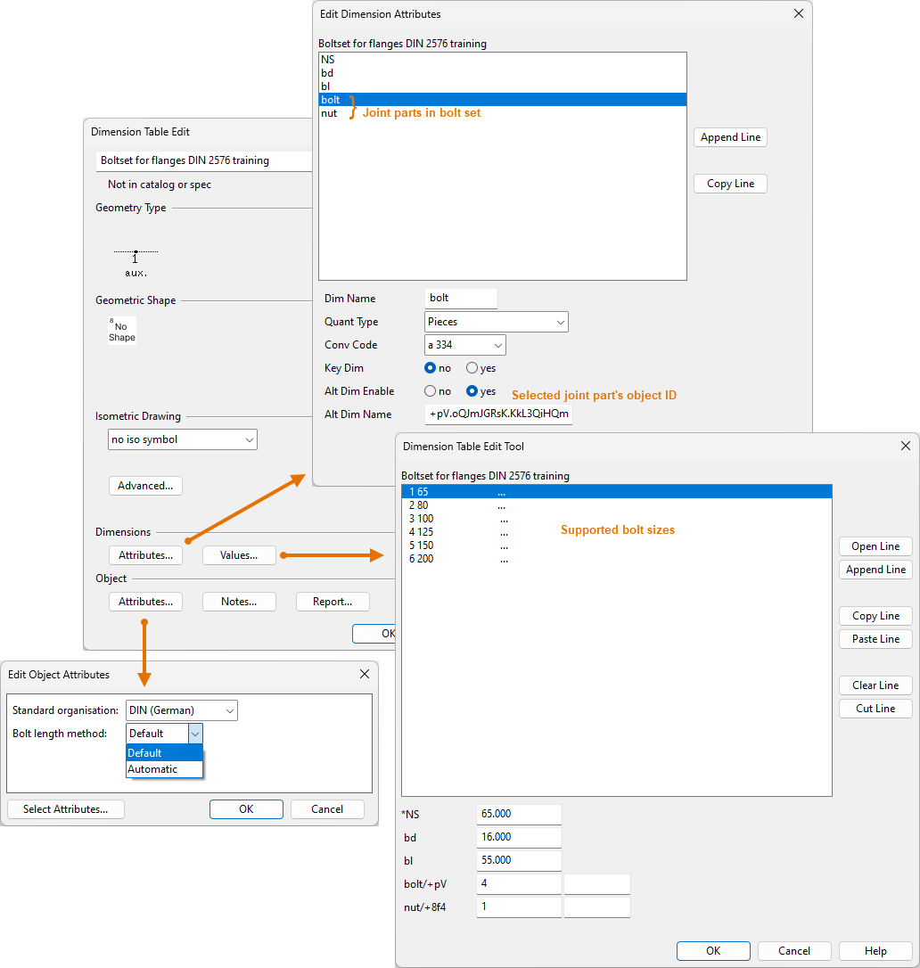
Dimension tables
In the Dimension Tables section, create dimension tables that describe the dimensions of the bolts, nuts, and washers included in bolt sets. The same dimension table can be used for all catalog parts with the same physical dimensions.
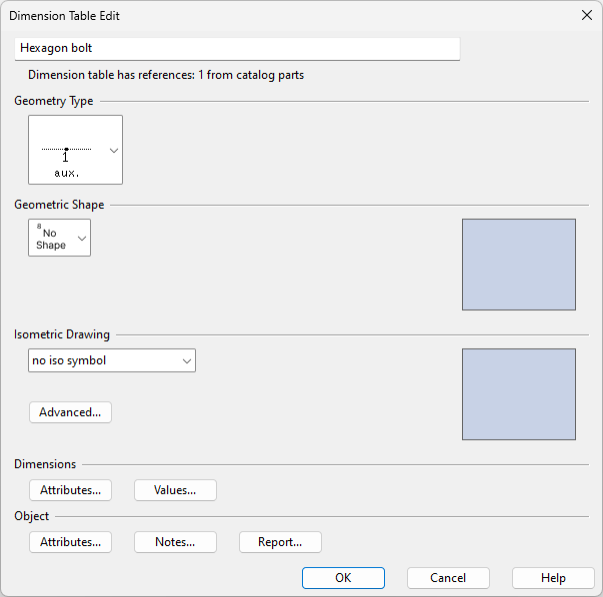
When defining these dimension tables, consider the following settings.
-
Geometry Type = DM_GT_AUXCOMP (3)
-
Geometric Shape = No Shape
-
Isometric Drawing = no iso symbol
-
Dimensions – Enter the dimensions of the part. Add all the values that one or more catalog parts may require.
- Diameter (for bolts, nuts, and washers)
- Length (for bolts)
- Mass
Next, create catalog parts for the bolts, nuts, and washers.
Catalog parts
In the Catalog Parts section, create catalog parts that describe the non-dimensional properties of the bolts, nuts, and washers included in bolt sets. For each catalog part, include a link to the dimension table that specifies the part's physical dimensions. For example, you may need multiple 'Hexagon bolt' catalog parts to account for variations in standards or materials, even though the bolt dimensions are the same.
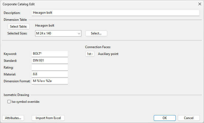
When defining these catalog parts, consider the following settings.
-
Description, Standard, Rating, Material – Enter the values to use. If pressure rating is specified, it must be equal to or greater than the pressure rating of the piping specification.
-
Dimension Format – Specify how to format the dimensions in the user interface and in outputs.
-
Select Sizes – Select the bolt sizes (Diameter x Length) from the dimension table. Add all the sizes that one or more bolt sets may require.
-
Connection Faces – Choose Auxiliary point.
-
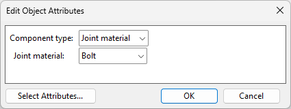
Attributes – Set the Joint material attribute to the appropriate type, such as Bolt, Stud bolt, Nut, or Washer.
Note: The Joint material attributes are required for visualizing the joint materials in the 3D model.
Next, create bolt sets that link the catalog parts of bolts, nuts, and washers into compatible sets.
Bolt sets
In the Bolt Sets section, create bolt sets that include a bolt, nut, and washer. For each bolt set, choose either fixed bolt lengths (default) or automatic bolt length calculation.
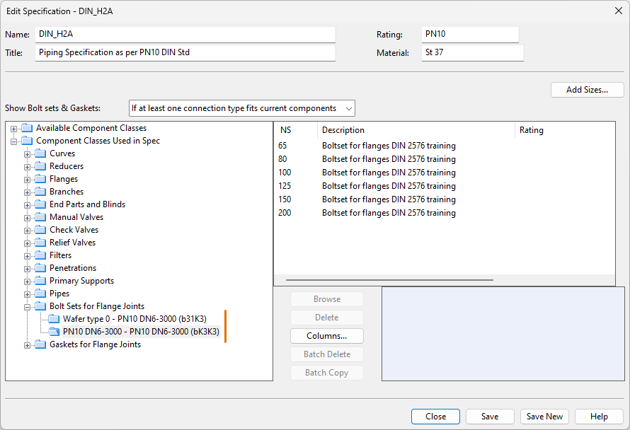
Piping specifications
In the Piping specifications section, use the Bolt Sets for Flange Joints category to specify which bolt set to use in flange joints with a specific nominal size and connection faces when the given specification is in use.
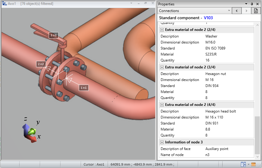
After inserting a flange joint into the 3D model, the properties of the joint materials determined through the piping specification can be viewed by selecting the component on either side of the connection and opening the Connections tab in the Properties pane.
For information on what happens when flanges do not use the same piping specification, see Assigning bolt sets and gaskets to flange joints.
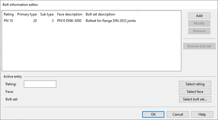
Bolt information
In the Bolt information configuration, you can assign a specific bolt set to a connection face with a specific pressure rating.
Note: The bolt information configuration is required for visualizing the joint materials in the 3D model.