Document
In CADMATIC P&ID, the File > Document menu contains the following commands.
Diagram Settings
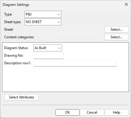
You can modify the general settings of the active diagram, such as the type of the diagram and the sheet that it is using.
Do the following:
-
Select File > Document > Diagram Settings. The Diagram Settings dialog opens.
-
Specify the new settings.
-
Type – Select the type of the diagram.
-
P&I – Select this option for a Piping & Instrumentation diagram. These diagrams describe the operations related to chemical engineering or process engineering at a more detailed level than what PFDs do.
-
Electric – Select this option for a diagram that describes the operations of an electrical system.
-
PFD – Select this option for a Process Flow Diagram that describes the major equipment and the primary process flows in a chemical engineering or process engineering facility at a fairly high level. A flowsheet might show, for example, how materials or objects are moved from one operative point to another for chemical transformation or physical assembly, and what is the flow direction between two consecutive operations.
Important: Only P&I diagrams publish the topological network of pipelines into the 3D model, which allows piping designers to use diagram-based pipe routing assistance. See P&ID integration in 3D routing.
Note: All diagram types publish EPD objects to COS, which allows P&ID to highlight components that exist in the 3D model. See Compare P&ID objects with 3D model.
-
-
Sheet type – Select the type of drawing sheet. The sheet defines aspects such as the page size and the appearance of the title box.
-
NO SHEET – The diagram does not use a drawing sheet.
-
DWG compatible – The diagram uses a DWG-compatible drawing sheet. For more information on this sheet type, see Drawing sheets (DWG).
-
Startup Script – The diagram uses a startup script to create the drawing sheet.
-
-
Sheet or Script – Select the DWG sheet or startup script to use.
-
Content categories – Select the Content Categories to use for this diagram.
-
Enter values for the attributes of the diagram; click Select Attributes to add or remove attributes.
-
-
Click OK.
Note: Depending on the changes you made, you may need to select Home > Label > Update > All labels to make the title box texts visible again, if they are not updating automatically as described in Automatic Update.
Change Annotation Property Defaults
File > Document > Change Annotation Property Defaults opens an object browser dialog for selecting the Annotation Property Defaults that the tools on the Drafting tab use in the active diagram.
Note: The project administrator can select the default Annotation Property Defaults for new diagrams in the Miscellaneous project settings.
Edit Title Box
You can edit the information shown in the title block of the active diagram.
Prerequisites
One of the following:
-
The diagram uses a DWG drawing sheet that includes a block with dynamic text fields defined as editable. See Drawing sheet's block editor.
-
The diagram uses a startup script-based drawing sheet. See P&ID Sheets.
Do the following:
-
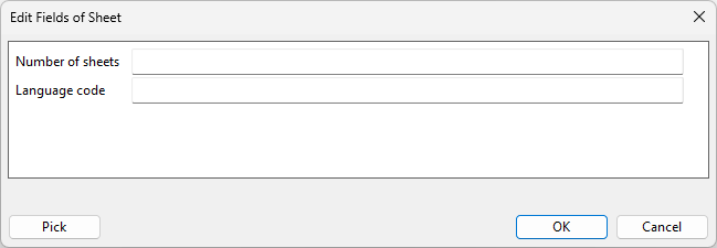
Select File > Document > Edit Title Box.
-
If the diagram uses a DWG sheet, the Edit Fields of Sheet dialog opens.
-
If the diagram uses a script-based sheet, the Edit Diagram Title Box Data dialog opens.
-
-
Edit the fields as required, and click OK. The changes are displayed in the diagram.
-
To update the changes to COS, select File > Save to COS Database. If the project administrator has enabled synchronization (see Synchronizing document attribute and title box values), the new values are also saved to the associated COS document attributes.

Edit Revision Table
File > Document > Edit Revision Table opens the Manage Revisions dialog where you can specify revision, designer, revision reason, revision date, and additional document revision information that administrator has defined in the project settings to be included, as described in Document Revision and Publishing.
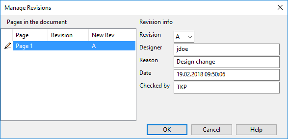
The Manage Revisions dialog shows the details of the current revision, and you can edit the values if needed. When you select a new revision from the Revision field and click OK, the new revision is added to the revision table label of the document, and the previous revision's values cannot be edited anymore.
The revision table data is updated to the diagram document when labels are updated with Home > Label > Update > Label or All Labels. Administrator can also set labels to be automatically updated, as described in Automatic Update.
Note: Administrator can set the revision number in diagram's title box to be automatically updated when diagram is published to 3D. This is done in the Database Table Manager, by opening the PI_CATALOG table and mapping the RevisionId column to the Generic Attribute "Publication revision" (.h7). See Database Table Manager.
Before designers can use the revision table, it must be correctly set in the P&ID sheet script and revision table script, as described in 'sheets' script and The revision_table Script, respectively.
Manage Reference Views
File > Document > Manage Reference Views opens the Manage Reference Views dialog where you can create, modify, and delete reference views. The View button hides the dialog, allowing you to browse the diagram; press Esc to return to the dialog.

A reference view is a rectangular area that you define to locate a diagram (or just some part of it) in the coordinate system of the 3D model. The settings of a reference view specify a reference point in model coordinates, so that diagram objects that are placed inside the reference view automatically get an estimated placement location in the 3D model. Pipe objects also get an estimated length. As a result, when the diagram is published to Plant Modeller and a designer adds an object to a work view, the location information provided by P&ID allows the cursor to automatically jump to the intended placement location.
Reference views are normally used together with reference drawings. Add a reference drawing from Drafting > Reference Drawing, as described in Reference drawings. When creating the reference view, set its scale to be the same as that of the reference drawing.
Creating a new reference view
Perform the following to add a new reference view to the active diagram.
Note: One diagram can have multiple reference views, but make sure they do not overlap.
Do the following:
-
Select File > Document > Manage Reference Views, and then click New. The Reference View dialog opens.
-
Enter the following information:
-
Name – Enter a name for the view. You cannot change the name later.
-
Min U, Max U, Min V, Max V – Enter the sheet coordinates to use, or click Pick to pick the starting corner and the ending corner from the sheet.
-
Direction – Select whether the view is a top view, front view, back view, or a side view.
-
Scaling – Specify the scale of the view, such as 1:100. The scale of the view should follow the scale of the reference drawing.
-
Reference Point – Specify the reference point of the view, first in diagram sheet coordinates (U, V), and then in 3D model coordinates (X, Y, Z). When specifying model coordinates, the Z value is important as it defines the height at which the reference view will be located in the model.
-
-
Click OK in the Reference View dialog, and then close the Manage Reference Views dialog.
-
In File > Options > Shared Project Settings > Model Coordinates, make sure that the option Use reference views to define diagram object coordinates is selected.

From now on, objects inserted to the diagram inside the reference view know their approximate placement coordinates in the 3D model.