Working with CADMATIC Electrical
CADMATIC Electrical and CADMATIC Plant/Outfitting can be used in the same design project, and there are various possibilities for sharing data between these applications.
About the software applications
CADMATIC Electrical is an electrical design software that provides design and documentation tools for electrical engineering and automation engineering: for building electrification (BIM/3D), industrial electrical and automation engineering, layout design of switchboards, and designing of distribution networks.
CADMATIC Plant/Outfitting is a 3D design software package for creating the 3D model and production documents for a whole construction project. This software package contains several applications that can contribute to and utilize the integration of electrical data.
-
In the CADMATIC Plant Modeller application, the Cable Router tool utilizes the 3D model to automatically route cables based on a nodal network created from the cable trays, cable pipes, and penetrations in the 3D model. Once the cables have been routed, the program can make an approximation of the required cable lengths and calculate the fill rates for the cableways and penetrations, allowing the cabling designers to ensure that the cables will fit to the selected routes. The cable routing tool also makes it possible to create drawings of the cable routes.
-
CADMATIC P&ID allows creating Process & Instrumentation Diagrams, and it is fully integrated with the Plant Modeller. The P&ID data and objects can be used as routing assistance in the 3D model.
CADMATIC eShare is an information management software for viewing the 3D model and the latest document publications, as well as additional data collected from other sources like PDM and ERP, via a single portal.
The picture below shows how data is transferred between CADMATIC Electrical and the other CADMATIC products.
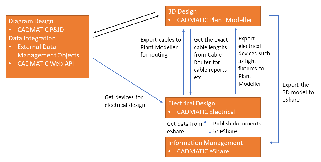
Accordingly, CADMATIC P&ID is one of the first modules that can be used in a new project . As soon as the required equipment, valves, and instruments are defined in a P&ID diagram, they can be transferred to CADMATIC Electrical as project devices, and utilized in cabling or wiring diagrams, drawings, and project object lists. The benefit of using a centralized import is that the imported data transfer objects are equally available in both Electrical and Plant Modeller, but if this is not needed, the Electrical software has its own import mechanism that can be used for importing devices.
CADMATIC Web API is the foundation for integration with any external software systems. Importing data from a PLM or ERP system and storing the data in COS as External Data Management (EDM) objects makes these objects available also in the device import list to Electrical. Also here the benefit is that the centralized import makes the device list and the attribute data equally available for users in CADMATIC P&ID, CADMATIC Plant/Outfitting, and CADMATIC Electrical, and the data is not linked to any specific design site but is replicated to everyone.
About integration of cables
In CADMATIC Electrical, the electrical designer can create cables, send them to the COS server as "Diagram Cable" objects, and also remove them from COS, if they become redundant. Eventually, the 3D model will have equipment, valves, and instruments added, and electrical cables routed between them.
In CADMATIC Plant Modeller, the 3D cabling designer can see the new cables sent by CADMATIC Electrical in the Not created diagram cables section of the Cable Router tool. The cables have head and tail equipment information, cable material information, and a set of extra attributes like notes, extra information status, and so on. When the head and tail equipment exist in the 3D model and the cable trays provide a sufficient route between the equipment, the cables can be automatically routed. The program calculates the route length, and CADMATIC Electrical can get the routed length of the cables and use this information in the electrical design.
Besides cables, also specific equipment can be sent from CADMATIC Electrical to Plant Modeller, using the COS object type "Electrical Device". A typical use case would be to send light fixtures, surveillance cameras, cash registers and other such electrical devices, or data for electrical cabinets, to the 3D model.
About integration of electrical devices
The integration of electrical devices is based on template IDs that identify a given part. If template IDs are not available for the Electrical product, the Plant Modeller user must manually select the correct part from COS when inserting equipment to the 3D model.
The CADMATIC example project contains templates for typical electrical devices such as light fixtures, signs, telephones, and surveillance cameras. These component models can have instance parameters defined in CADMATIC Electrical, but if instance parameters are not defined, then the default size is used when inserting the part. Project administrators can also make their own templates.
Electrical devices require systems and data attributes to be mapped.
Priority order of electrical device attributes
Importing an electrical device from CADMATIC Plant/Outfitting to CADMATIC Electrical imports the attributes from the associated integration objects. If multiple objects have the same attribute but their values are not the same, the program selects the attribute value to use based on the following priority order:
-
EDM Object
-
EPD Object
-
3D Model Object
-
Component Model
-
Part Size
For example, if both EPD object and Component Model have the attribute "Requires electricity" (.IJ), the import takes the attribute's value from the EPD object.
Modeling electrical devices in Component Modeller
When creating a component model (GDL) for an electrical device in Component Modeller, do the following:
-
Use X, Y, Z to name the parameters (according to the axis directions), and define all parameters as instance parameters that have minimum and maximum values. See Parameters pane.
Note: Some equipment might not need all the parameters if they are irrelevant to the model. Parts such as levers and buttons are not parametric.
-
Set the component's origin on the surface where the equipment is attached to a wall or ceiling.
The location must match the location of the origin of the component in the Electrical application.
Note: The component model does not need other nodes than the node in the origin.
-
Set the component's orientation to match the orientation of the component in the Electrical application.
-
Define at least one parametric model for the component and assign the attribute "Electrical Template ID" (_S0) to the parametric model. See Parametric models.
Setting up the integration
Before electrical designers can use the integration between CADMATIC Electrical and CADMATIC Plant/Outfitting, the administrators of the applications must do the following:
In CADMATIC Plant/Outfitting
-
Set up the design projects in CADMATIC Plant/Outfitting and CADMATIC Electrical as usual, and add the current electrical document to the project with the Add document to project command of the Electrical project tree.
-
Set up the COS server:
-
Create COS User Accounts with Windows authentication for the CADMATIC Electrical users who will be using the integration.
-
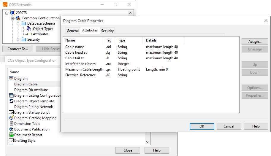
Enable cable-related Attributes to be exported from CADMATIC Electrical by assigning the relevant attributes to the "Diagram Cable" COS object type.
-
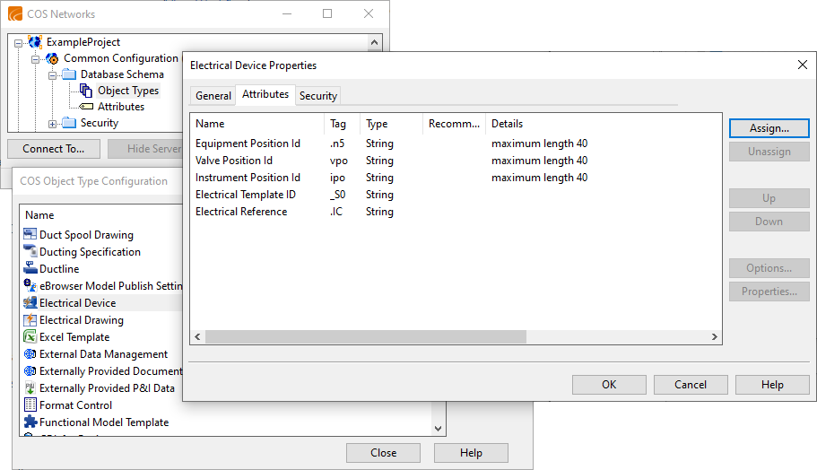
Enable device-related Attributes to be exported from CADMATIC Electrical by assigning the relevant attributes to the "Electrical Device" COS object type.
-
-
Create a Plant Modeller service instance that manages diagram integration (transferring of data between P&ID and Plant Modeller) and (if needed) publishes documents to eShare. See Plant Modeller services.
-
If eShare integration is to be used, make sure the Plant Modeller project is connected to eShare. See Managing project settings.
In CADMATIC Electrical
-
Set up the design project as usual.
-
In the project tree, use Add document to project to add the current electrical document to the project.
-
Connect the project to COS:
-
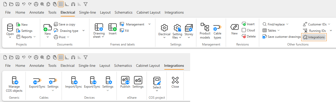
Open the Integrations tab by selecting the Electrical tab > Other functions group > Integrations.
-
Select the Integrations tab > COS project group > Select.
-
In the Connect to COS project dialog, select the Plant Modeller project's *.pms folder.
The Electrical software connects to the COS project database and enables the other commands on the Integrations tab. See Using the integration.
Note: If the COS network uses replication, this action is to be performed on the site where Electrical is installed. The integration-related commands will then be run on that site, and the integration data is replicated in the COS network as usual.
-
-
Define the integration mappings. See Defining integration mappings.
Defining integration mappings
On the Integrations tab, you can map data defined in CADMATIC Electrical to data defined in CADMATIC Plant/Outfitting to enable correct data transfer between the applications.
-
Select the Cables group > Settings menu > Map cable types to map Electrical cable types to Plant/Outfitting cable types (catalog part IDs). Multiple Electrical cable types can be mapped to a single Plant/Outfitting cable type.
Note: The cable type mappings are stored in COS; the other mappings are stored in the Settings subfolder of the Electrical project.
-
Select Cables group > Settings menu > Map cable data to map Electrical cable data to Plant/Outfitting cable attributes. Cable data travels only in one direction: from Electrical to Plant/Outfitting.
-
Select Cables group > Settings menu > Map systems to map Electrical cable systems to Plant/Outfitting cable systems. Multiple Electrical cable systems can be mapped to a single Plant/Outfitting cable system.
-
Select Cables group > Settings menu > Map interference classes to map Electrical interference classes (the "Class" property) to Plant/Outfitting interference classes. Multiple Electrical interference classes can be mapped to a single Plant/Outfitting interference class.
-
Select Devices group > Settings menu > Map data for device import to map Electrical device data to Plant/Outfitting device attributes, if for example instruments defined in published diagrams are to be imported to Electrical. The mapping dialog shows the Plant/Outfitting attributes that have been defined as integration attributes in CADMATIC P&ID. The P&ID administrator defines these attributes in the Database Table Manager tool by selecting the COS tag value of the Externally Provided P&ID Data (EPD) object to use for a given SQL column, so that it will be published as an integration attribute.
Note: Another source for getting device data (for example, for electrical cabinets) to Electrical can be PLM or ERP software, if such integration has been created via XML import or CADMATIC Web API. The imported devices will also list all objects which can be found in COS as External Data Management (EDM) objects.
-
Select Devices group > Settings menu > Map data for device export to map Electrical device data to Plant/Outfitting device attributes, if devices such as light fixtures are to be sent from Electrical to Plant/Outfitting and the data is to be displayed in Plant/Outfitting. The mapping dialog shows the Plant/Outfitting attributes that have been added to the "Electrical Device" COS object type.
-
Select Devices group > Settings menu > Map system for device export to map Electrical systems to Plant/Outfitting systems. Multiple Electrical systems can be mapped to a single Plant/Outfitting system.
Using the integration
In CADMATIC Electrical, the commands that relate to integration are displayed on the Integrations tab. If this tab is not open, you can open it by selecting the Electrical tab > Other functions group > Integrations.
Export or synchronize cables | Import or synchronize electrical devices | Export or synchronize electrical devices | Publish documents to eShare
Export or synchronize cables
You can use the Export/Sync command to export cables from CADMATIC Electrical to the COS database of Plant/Outfitting. The COS object type of cables exported from Electrical is "Diagram Cable", which enables the Cable Router to manage them in the same way as cables defined in the P&ID application. If cables are modified in Electrical, you can use this command to update the cables in COS. After the cables have been routed in the Cable Router, you can use this command to retrieve the cable lengths into Electrical. If cables are deleted in Electrical, you can use this command to remove them from Plant/Outfitting.
Prerequisites
-
Cables have been drawn in Electrical between head and tail objects. When using integration, the cable ends cannot be defined as virtual locations in the Cable Router tool.
-
Mappings have been defined in Integrations tab > Cables group > Settings menu > Map…
Do the following:
-
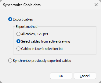
In Electrical, select Integrations tab > Cables group > Export/Sync. The Synchronize Cable data dialog opens.
-
Select whether to export or synchronize cables.
-
If exporting cables, select whether to export all cables or just specific ones.
-
If synchronizing cables, the tool will update previously exported cables, remove cables that no longer exist in Electrical, and retrieve the already routed cables and their lengths to Electrical.
-
-
Click OK.
The data is updated to COS. In the Cable Router, the cabling designer can select a new cable for routing from the Not created diagram cables view. For more information on the Cable Router, see Cables.
Note: If a cable is changed after creating it in the 3D model, the changed attribute values are shown automatically for the diagram cable, but the From/head and To/tail changes are only visible when using the Compare tool of the Cable Router. There is also the possibility to change the attribute values in Cable Router, if the COS tag has been assigned to the "Cable" COS object type. The differences in attribute values are also visible in the comparison tool.
Import or synchronize electrical devices
You can import electrical devices from CADMATIC Plant/Outfitting to CADMATIC Electrical. This import allows the electrical designers to get device data and position IDs as soon as they are defined in a P&I diagram.
In the COS database, the type of the object can be Valve, Equipment, or Instrument. The attribute that specifies whether the part needs electricity can come either as a direct attribute or via the referenced catalog part (or part size), EPD object (created by P&ID), EDM object (created by third-party software such as ERP or PLM), or model object linked to the EPD or EDM object.
After importing electrical devices, you can use the same command to update them.
Note: There are two versions of this importer: old and new (2024T2–). Do not use both at the same time.
New importer
In CADMATIC Electrical, you can import electrical devices from the COS database into objects and add the objects and their mappings into the Electrical database.
Prerequisites
-
(Optional) A published test diagram or EDM objects created to the project, for example, via the CADMATIC Web API (a REST API). This is for making sure that you map the data correctly.
Do the following:
-
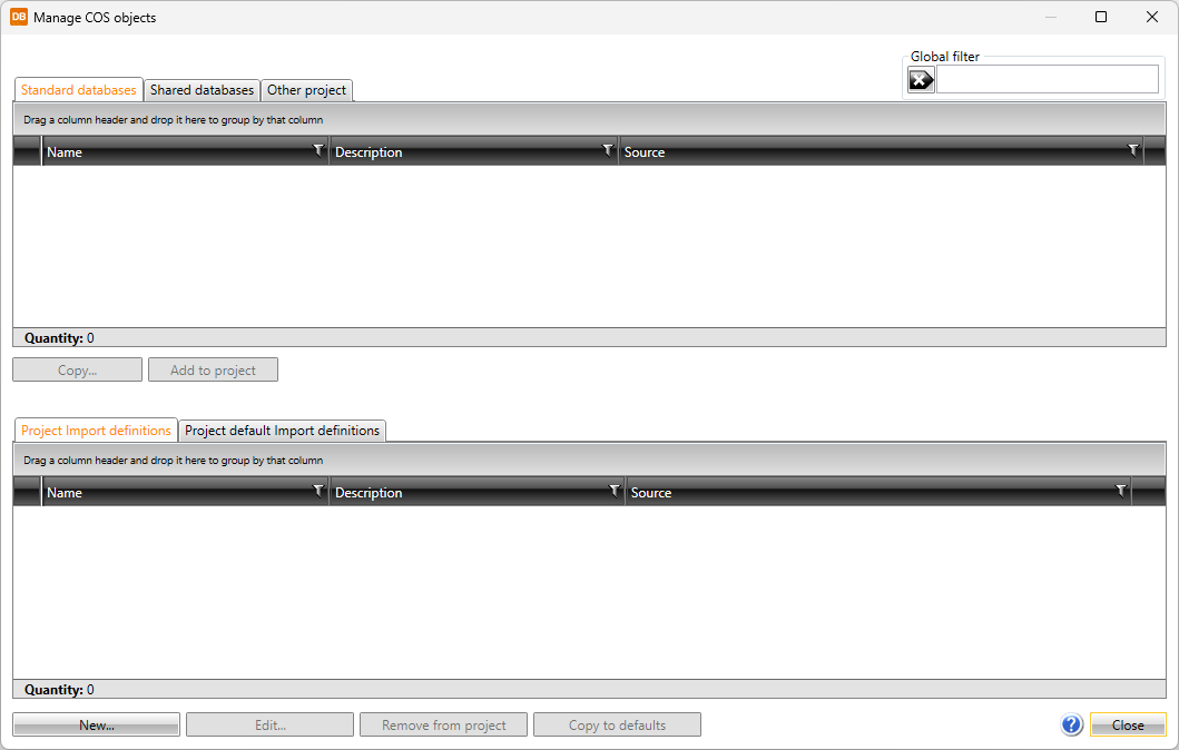
In Electrical, select Integrations tab > Generic group > Manage COS objects. The Manage COS objects dialog opens.
-
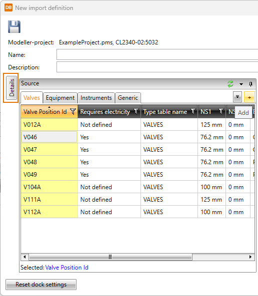
Click New. The New import definition dialog opens, listing the available COS objects in the Source pane.
-
In the Name field, enter a name, if you want to save this import definition for future use.
-
In the Source pane, set the dialog to display the necessary information.
-
You can add a new source tab by clicking the + (Add) button.
-
You can set column filters to display only COS objects relevant to you.
-
You can show currently hidden source attributes by right-clicking the header row and selecting Show columns.
-
You can show more information about a COS object by selecting the object and clicking Details on the left.
-
-
Specify how to map COS attributes to Electrical by dragging fields from the Source pane to the appropriate column on the Devices tab. Use the Generation rule and Common Regex options to adjust the generation of the mapping rules.
 Show/hide image
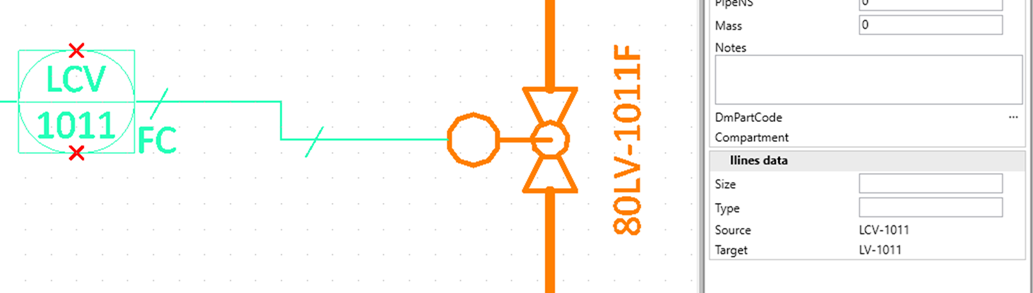
The COS items are primarily devices, but circuits can also be imported. This example shows how instruments defined in P&ID are integrated into Electrical. The circuit is created from the instrument's Tag Name and other data. The database recognizes the instrument lines ('iline') defined in P&ID, and the devices are automatically categorized correctly, based on the from/to data derived from the iline.
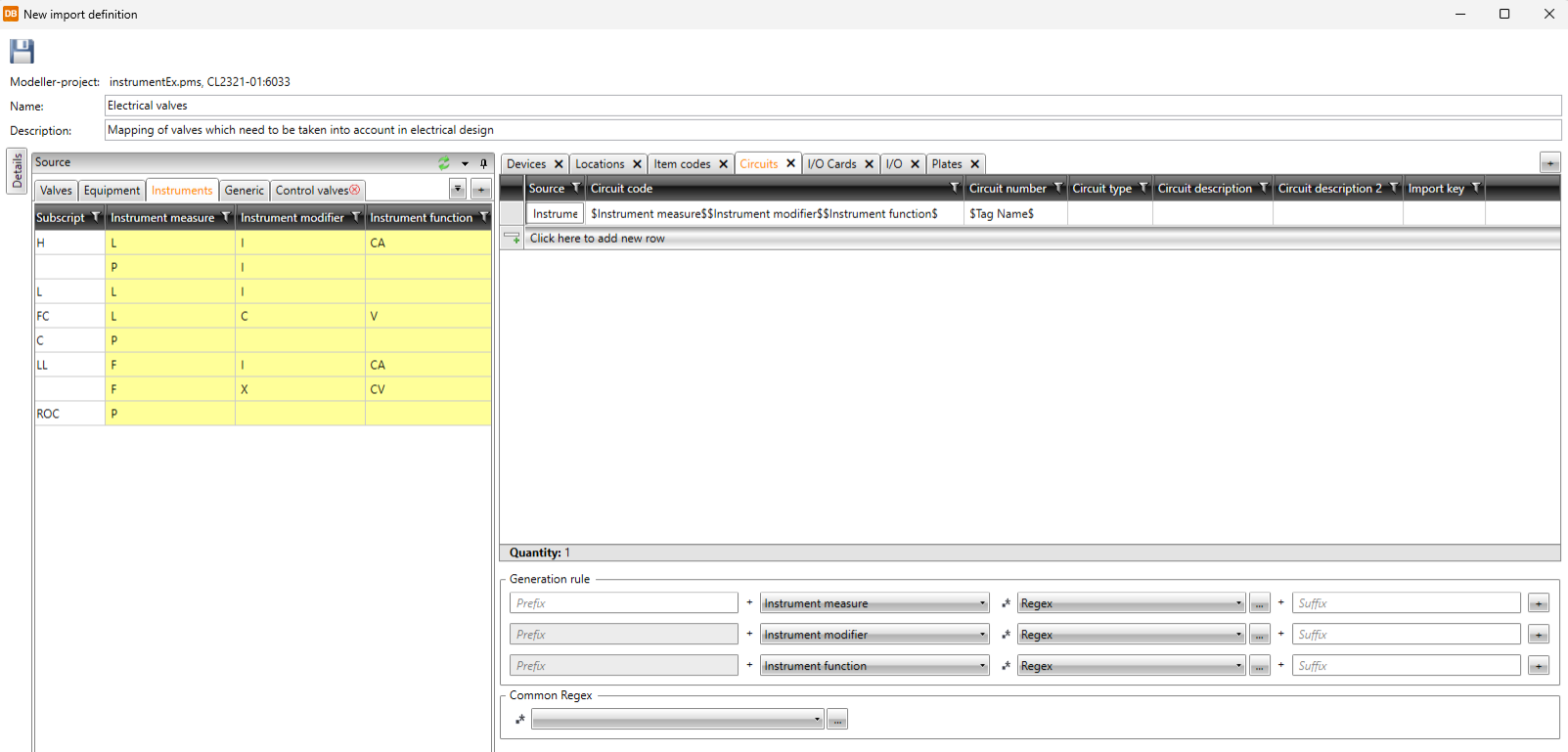
In the example diagram below, 'LCV-1011' will be a circuit and 'LV-1011' will be a device in Electrical.
-
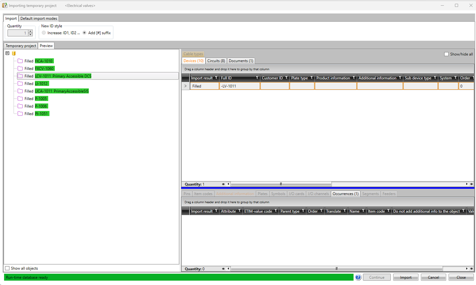
When the required mappings have been made, click Import. The Importing temporary project dialog opens. Here, you can see a preview of how the mappings will be used to import data to Electrical.
-
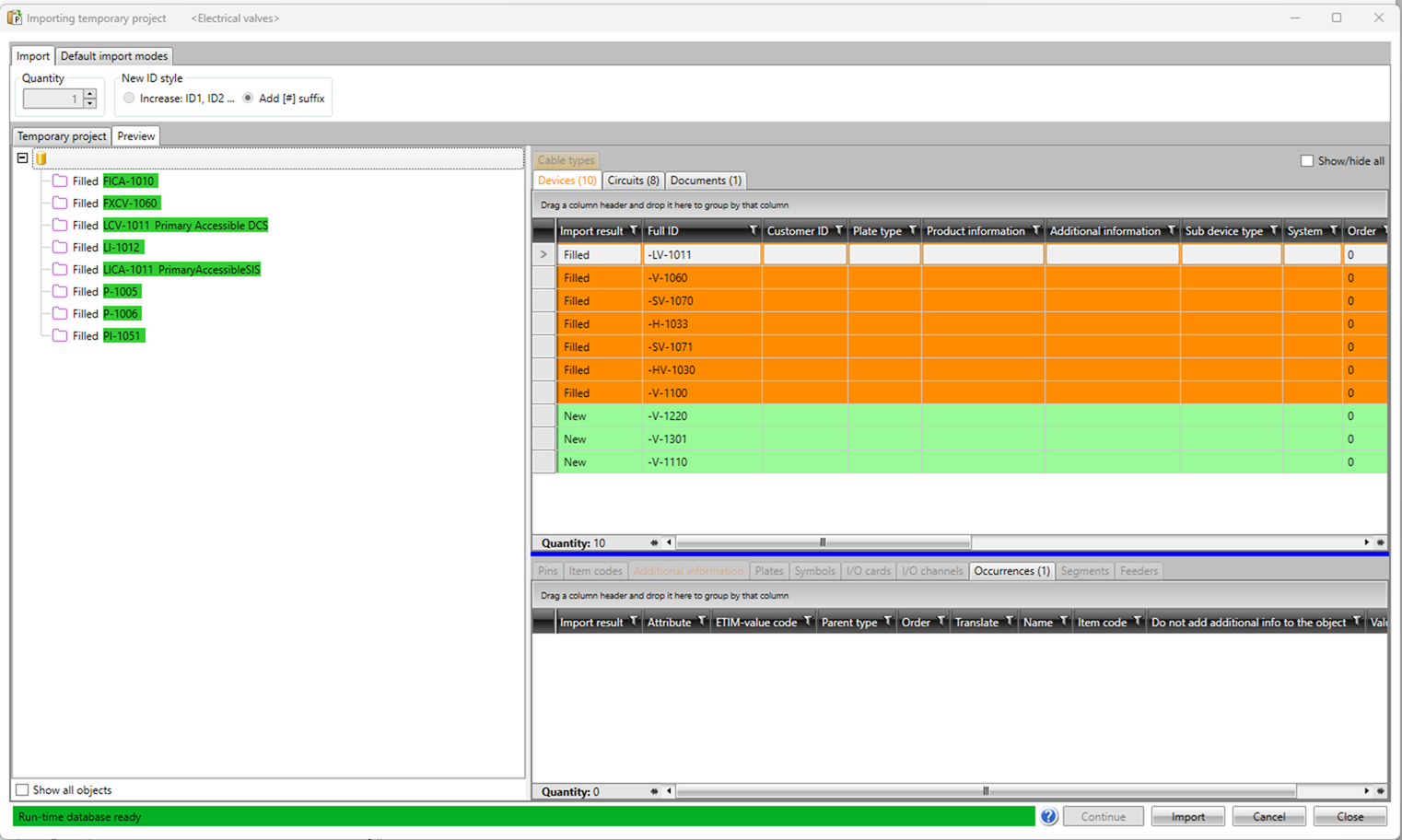
You can still change the mappings by clicking Close to return to the mapping dialog. Otherwise, click Continue. Now, you can select a category from the left to display which devices will be in that category. If you repeat the import later, the dialog displays which objects are new.
-
Click Import. The object hierarchy is created, and the devices are available in the Project tree. Now the integrated objects with their mapped attributes are available for the project's documents and lists.

Old importer
In CADMATIC Electrical, you can import electrical devices from the COS database into the Electrical database.
Prerequisites
-
Mappings have been defined in Integrations tab > Devices group > Settings menu > Map data for device import.
Do the following:
-
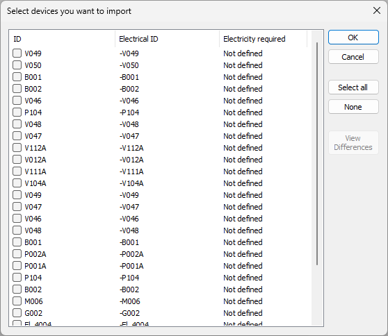
In Electrical, select Integrations tab > Devices group > Import/Sync. The Select devices you want to import dialog opens, displaying a list of objects which have a position ID defined in either P&ID or some external software and which are present in the COS server as EPD and/or EDM objects.
-
Select the devices you want to import, and click OK.
The data is imported into CADMATIC Electrical and is available when inserting devices into drawings.
Export or synchronize electrical devices
You can export electrical devices from CADMATIC Electrical into the COS database. The COS object type is "Electrical Device".
The exported electrical devices are available when inserting equipment into the 3D model. The insertion is more automatic if the exported device data includes location and transformation, as well as a template ID. The template ID is an attribute of the parametric model in Plant Modeller. In Electrical drawings, a device must have a 3D occurrence symbol that has the same name as the template ID; the 3D symbol is usually defined in the Electrical product model. If the ID is not available, the Plant Modeller user must select the appropriate part from the part library and specify the correct location manually. For information on inserting electrical devices and other integration objects to the 3D model, see Insert.
The devices that have been inserted to the 3D model form a link between the "Electrical Device" COS object and the inserted 3D model object. The 3D model objects work exactly like any other 3D model objects, but they have additional data attributes that come from CADMATIC Electrical. Notice that a single 3D model object can be linked to several integration COS objects if they come from different sources. See Integration object attributes.
If any information, such as a mapped attribute or system changes in Electrical, then the device must be exported again.
Prerequisites
-
Integrations tab > Devices group > Settings menu > Map data for device export.
-
Integrations tab > Devices group > Settings menu > Map systems for device export.
Do the following:
-
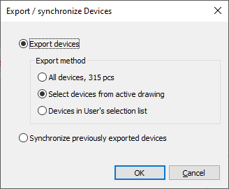
In Electrical, select Integrations tab > Devices group > Export/Sync. The Export / synchronize Devices dialog opens.
-
Select whether to export all devices or just specific ones.
-
Select Synchronize previously exported devices if you want existing devices to be updated or removed (if they no longer exist in Electrical).
-
Click OK.
Publish documents to eShare
CADMATIC Electrical can publish documents to CADMATIC eShare. This is similar to publishing documents from the CADMATIC Plant/Outfitting applications (Plant Modeller, Piping Isometrics & Spools, P&ID), as outlined in Working with CADMATIC eShare. However, documents published by Electrical are stored as files, while those published by the other applications are stored in the COS database.
Prerequisites
-
In Plant/Outfitting, the eShare settings enable the project to connect to eShare, and a Plant Modeller service instance is publishing documents to eShare, as described in Scheduling document publishing.
-
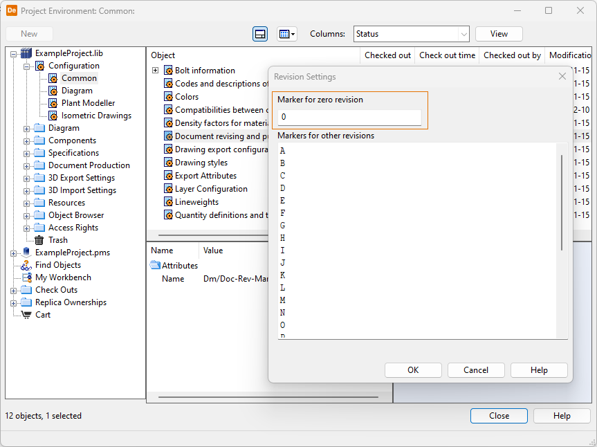
Both Electrical and Plant/Outfitting are using the same method (letters, numbers) for indicating document revisions. If Electrical is using the default zero revision "0", then Plant/Outfitting must also use "0" as the zero revision in the Document revising and publishing settings.
-
In Electrical, the settings for creating PDF files are defined in File > Print > Print settings.
-
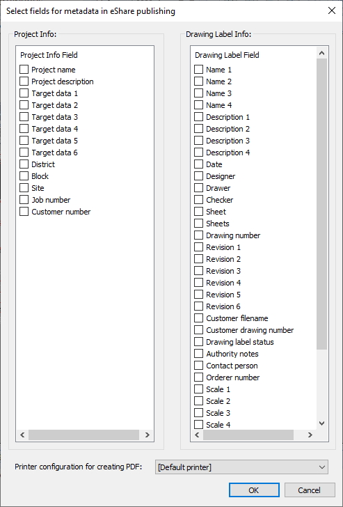
In Electrical, the metadata to include in the published document is selected in Integration tab > eShare group > Settings.
Do the following:
-
In Electrical, select Integrations tab > eShare group > Publish. The Select the drawings you want to publish dialog opens.
-
Select the drawings to publish, and click OK.
The publishing creates a PDF version of the electrical drawing. A multi-page document is automatically printed as a multi-page PDF. In eShare, the position IDs of the objects automatically link the drawing object to the corresponding object in the 3D model, or to some other type of source data which is available to eShare.
Error log
If reading electrical devices from Plant/Outfitting to CADMATIC Electrical fails, the application shows a simple error message and an error code. For more details, open the error log file:
%AppData%/elec_dll_log.txt
External Data Management (EDM) objects
CADMATIC Electrical Premium Online Help: Integration between Electrical and Plant Modeller