Cable Tray

On the Cabling tab, in the Cable Tray group, you can use the following tools.
Route
You can perform the following to route cable trays in the 3D model. Before routing, consider the following guidelines:
|
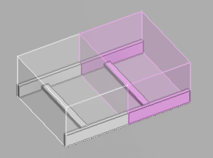
Good routing practices |
Bad routing practices |
|---|---|
|
|
Tip: As a rule of thumb, if the ends of cable tray parts are so close to each other that they look connected, ensure that they really are connected. The project administrator can adjust the allowed maximum distance and angle between connected tray ends in Tolerances.
Prerequisites
-
The project environment contains the necessary elements.
 Show/hide details
-
Cable tray catalog parts.
-
Cable penetrations as equipment.
-
Systems with line definition for each tray type and tray material; each line has one or more specifications.
-
-
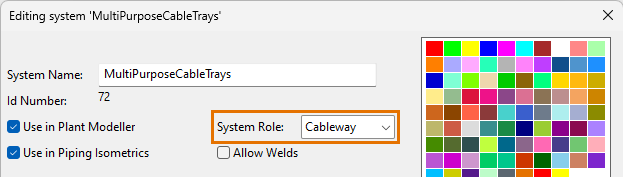
If cables are to be routed in a cable way or cable penetration, its System has System Role set to "Cableway".
-
To use flexible curves that can bend horizontally or vertically in any angle, the catalog part that the specification assigns for the bend must define angle as an instance parameter.

Do the following:
-
Optionally, use the Model Tree pane to select the System the model object is to use.
-
On the Cabling tab, in the Cable Tray group, click Route (Alt+T).
-
Navigate to the start point of the new cable tray. See Navigate and connect.
-
Start the routing from the specified location with a suitable context-menu command.
Show/hide details
-
Use the Join (J) command to join the new part seamlessly to an existing cable tray and inherit all the properties from the existing part.
-
Use the Connect (P) command to connect the new part to an existing cable tray so that there is a seam between the parts.
The Select Cable Tray and Specification dialog opens and you can allow all properties to be inherited from the connection or change the properties as required.
-
Use the Free End (Space) command to start a completely new route from the specified point.
The Select Cable Tray, Specification and Size dialog opens.

-
-
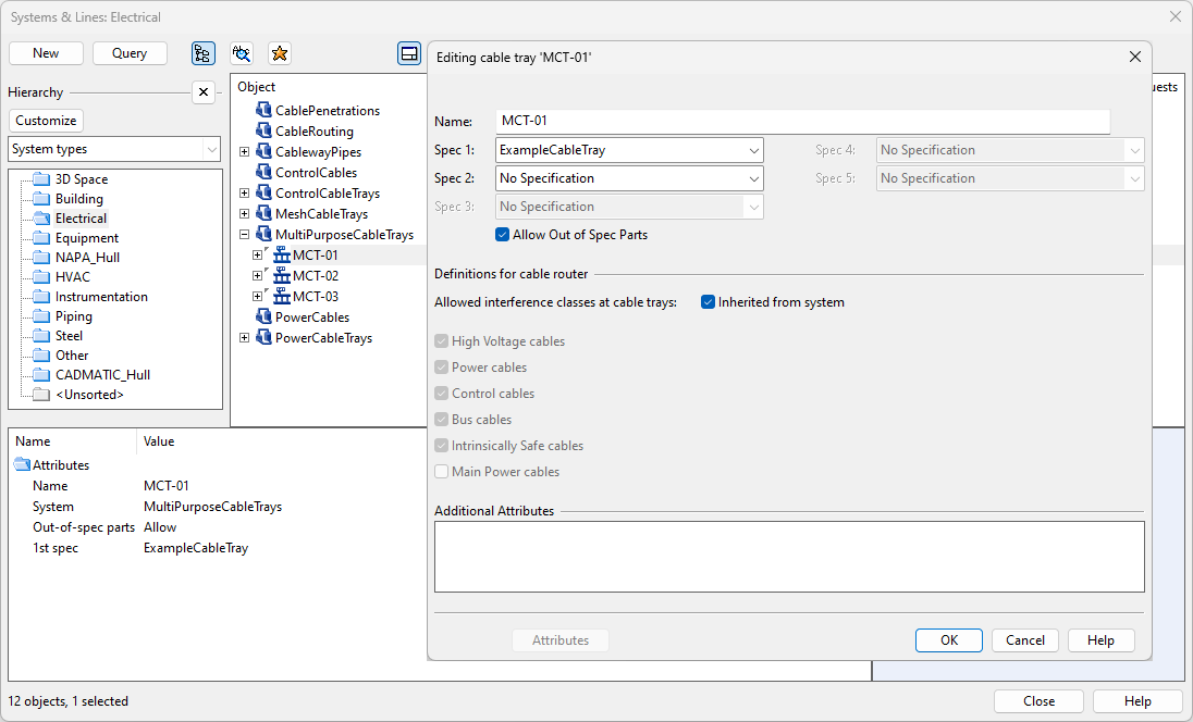
Specify the settings for the new cable tray, if they were not inherited.
Show/hide details
-
System – Select the System to use. You can use the System that is currently selected in the model tree, select the System from the drop-down list, or select the System from the object browser.
-
Line – Select the cable tray "line".
You can use the Search field to find the required line. Also regular expressions are supported.
Show/hide details
-
The columns that are searched are predefined. Note that the search string can also be found from a column that is not currently visible: click Columns to define which columns to show.
-
The search string can be found from any part of the target string, and the search is not case-sensitive.
Search string…
Finds…
line
strings that contain LINE, such as "MyLine-01"
-
You can use a dot to represent a single required character.
Search string…
Finds…
....line-01
strings where LINE-01 is preceded by at least four characters, such as "AA_MyLine-01"
-
You can use advanced regular expressions if you add R: to the beginning of the search string.
Search string…
Finds…
R:[ad]
strings that contain A or D, such as "DIN_H2A"
R:[a-d]
strings that contain A, B, C or D, such as "CW-001"
R:^k
strings that start with K, such as "K51"
R:[\s]
(or just R: followed by one space character)
strings that contain a whitespace character, such as "My Line 01"
-
-
Specification – If several specifications are available, select the one to use.
-
Size – Select the size of the cable tray. Only sizes that have material defined in the cable tray specification are listed. (This field is not displayed if the size has been fixed by picking the starting point from an existing connection.)
-
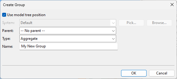
Group – Select whether to assign the model object to an existing or new group.
-
Click OK.
-
-
If you chose to create a new group, the Create Group dialog opens. Define the properties of the group to be created, and click OK.
-
Start routing the cable tray in the 3D model by picking a routing point and clicking Space to complete the segment. The program automatically inserts a straight part, bend, or riser, as defined in the cable tray specification. The default reference point is the centerline, but you can change it with Set reference point (B).
-
You can use context-menu commands, for example, to change the specification, to enable or disable collision control, to rotate the last segment, to force the use of miter joints instead of curves, or to insert a cable tray component.
Show/hide example
To add a component to the route, do the following:
-
Press Insert or select Add component from the context menu. The Select Component – Add To Cable Tray dialog opens.
-
Select the specification, component class, functional description, and size to use.
-
In the Joint entered first field, select which end of the component to connect first. This defines the orientation of the component in the model, but you can also correct the orientation afterward, if needed.
-
Click Details if you want to view the selected component in an object browser window.
-
Click OK. The component is added to the model.
-
If the orientation is incorrect, use the command Change orientation (Home) to adjust it. You can also rotate the component along its connection axis (Page Up / Page Down).
-
You can use the commands Undo (U) and Redo (Ctrl+Y) to remove or restore cable tray segments and components, if needed. Undoing the first added segment will cancel the routing operation.
-
-
End the route.
-
You can use Connect (P) or Join (J) to route the last cable tray part to the connection node of an existing cable tray.
-
You can press Enter to complete the route at the last added cable tray part.
-
If you press Esc, the program cancels the routing and removes all the parts that you inserted.
-

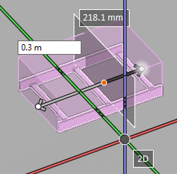
Cut
Use the Cut tool to cut a straight cable tray into two separate pieces.
When the tool is enabled, moving the cursor over a cable tray finds the nearest centerline point, and the designated point and the cut plane are visualized to the user. There are also text labels that indicate distance from the centerline endpoints, and the distance values can be manually edited to move the cut point to a specific location.
If the currently designated location is not valid, for example if the cut would make the cable tray too short, the cut plane turns red and a message indicates why cutting is not allowed. The cutting point can also be on a traverse bar of a ladder-type cable tray; when the cut is made, the visualization automatically re-positions the bars.
Do the following:
-
On the Cabling tab, in the Cable Tray group, click Cut.
-
Move the cursor to the location where the cut is to be made.
You can also define the exact distance from an endpoint; press Ctrl+Tab to activate the required distance value field, edit the value as required, and then press Enter to set the cut point in that location.
-
Press Space or Enter, or click with the mouse, to perform the cut. Both sides of the cut can now be managed as individual parts.
-
You can continue to cut cable tray objects, or press Esc to exit the cut tool.
Join
Use the Join tool to join two straight (connected) cable tray segments into a single cable tray. The resulting cable tray cannot exceed the maximum length of a cable tray part.
Do the following:
-
On the Cabling tab, in the Cable Tray group, click Join.
-
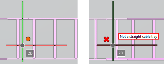
Move the cursor near the location where the join should be made. When a connection point is displayed, click to join the cable trays. If the cable trays cannot be joined, for example because one is a cable tray component instead of a straight cable tray piece, a red X is displayed and a message indicates why joining is not possible.
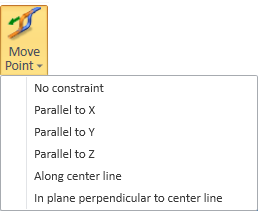
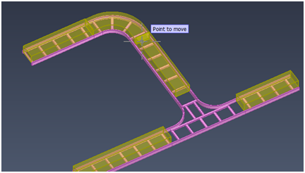
Move Point
In the Cable Tray group, select a suitable Move Point command to change the geometry of cable trays by moving one connection point. All connected parts are moved along, including Cable Way Spaces and objects that are used to build the cable routing network, and collision control checks for possible collisions. Performing the move requires that the geometry contains enough straight parts so that all the required adjustments can be made.
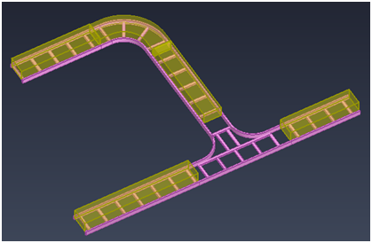
In the following example procedure we move a branch run closer to the main run.
Do the following:
-
On the Cabling tab, in the Cable Tray group, select Move Point > Along center line, and navigate close to the connection point that you want to move.
-
Use Move to nearest connection (Q) and then Connection near point (Space) to select the connection point, and press Enter to accept the point.
-
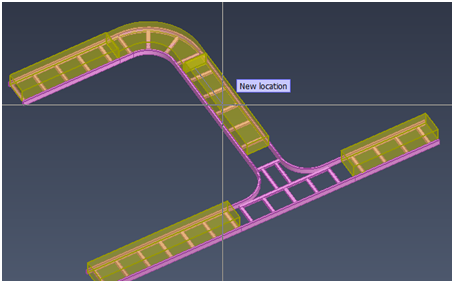
The cursor is constrained to move only along the centerline of the cable tray, and you can select the new location of the connection point.
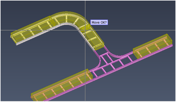
When you accept the new location, the required changes are made to the geometry, the modified objects are highlighted, and you can browse the results.
-
Press Enter to accept the move, or U or Esc to undo the move. The move also supports the Undo and Redo commands.
Delete
Use the Delete tool to delete cable tray segments and components. This also deletes the Cable Way Space, if it exists.
Do the following:
-
On the Cabling tab, in the Cable Tray group, click Delete.
-
Select the cable tray objects that you want to delete, and accept the set.