Associative annotations
In the document editor, the drafting tools allow labels and dimensions to be associated with the 3D model. If the 3D model is changed later, the program can check the associations, and then prompts the user to update the annotations that are no longer matching the 3D model.
Enabling associative annotations
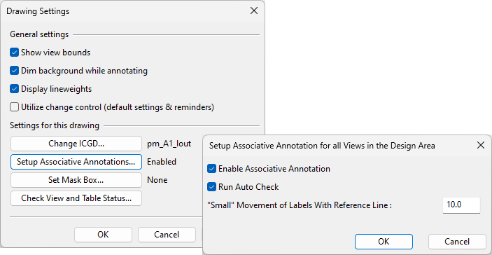
In the Settings of the active document, you can do the following:
-
You can enable or disable associative annotations. After enabling this function, you can use a 3D navigation command while inserting or editing an annotation to associate the annotation with the 3D model. The associations are preserved even if you later disable the function.
-
You can enable or disable automatic checking of associative annotations. After enabling this function, you can activate a drawing view to run the check that compares the associative annotations with the current 3D model.
Creating associative annotations
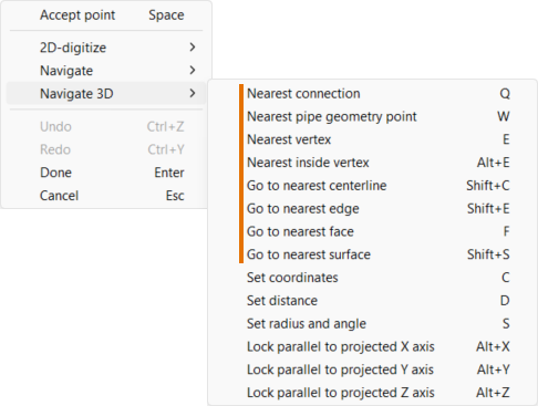
When you have enabled associative annotations in the active document, you have the ability to associate labels and dimensions with the 3D model. This is done by using a 3D navigation command when inserting or editing the annotation. For more information on 3D navigation commands, see Navigate and connect.
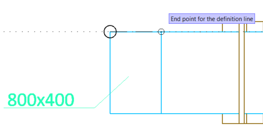
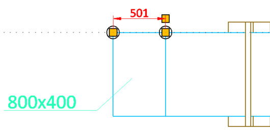
You can use a 3D navigation command to navigate to a connection point, geometry point, or geometric feature when you are picking the target of the annotation. Using a 3D navigation command shows a small circle in the location you navigated to. If you then pick that location, the size of the circle increases to indicate that the 2D point is now associated with the 3D model.
Starting to edit an annotation shows large circles around the 2D points that are associated with the 3D model.
If you move an associative annotation in the drawing, the associations are broken. They might also be broken if a 3D designer cuts a routed 3D object (beam, pipe, air duct, cable tray); those annotations that remain fully connected to the "head part" (original object) keep their associativity, while those annotations whose 3D points are now in the "tail part" (new object) lose their associativity.
If an annotation has lost its associations or was never associative, you can use a 3D navigation command on its reference points to (re-)associate it with the 3D model.
Checking associative annotations
When you have enabled automatic checking of associative annotations in the active document, selecting a drawing view from the Annotating menu of the document editor checks whether the associative annotations in that view still match the 3D model.
Checking of labels can have the following results:
-
If the 3D object no longer exists or is no longer visible (for example, due to a content rule) in the view, the label is to be removed.
-
If the 3D object has moved, the label is to be moved by the same amount.
If the label has a reference line and the movement is small, only the end point of the line is to be moved.
-
If the 3D object has data changes, the data is to be re-extracted and formatted as the label definition specifies, and the label is updated. If you have edited the label data manually, those changes will be lost.
Checking of dimension lines can have the following results:
-
If a 3D point no longer exists, the point is to be removed from the 2D object.
If this is not possible (for example, in the case of a dimension line with two endpoints), then the 2D object is removed.
-
If a 3D point has moved, the 2D point is to be moved by the same amount. This updates the appearance of the 2D object accordingly.
In the situations listed above, the Update Associative Annotations dialog opens for managing the situation, as described in Updating associative annotations.
Additional information about associativity
The 3D navigation commands Move to nearest connection (Q) and Move to nearest geometry point (W) use the object ID and the node ID of the point within the object to address the associated point. For piping parts, the recorded node number is the ID of the geometry point, and the association does not change even if the order of the parts in the pipeline gets changed, for example, when pipes are joined.
Plant Modeller tries to avoid addressing points via objects that can be cut. In a connection or joint, Plant Modeller always selects the object that stays "rigid". When an object gets cut, then the point addressing of the second end point is radically changed.
If you navigate to a geometric entity (vertex, edge, face), Plant Modeller associates the 3D point with the resulting 2D point by storing the ID number of the model object and the position of the 3D point in the local coordinate system of the object. This way the association can be maintained over any rigid body transformations. However, if the geometry of the object is modified, the program might not be able to synchronize the 2D point with the original 3D point anymore.
When Plant Modeller later examines these associations, it does not re-execute the original navigation commands but simply obtains the transformation matrix of the object and uses that to transform the local point into model coordinates, and from there to view coordinates. These coordinates are then compared with the associated 2D point, and if they are not the same, then the 2D point is moved. This in turn updates the 2D entity (line or dimension line) to which the point belongs.