Edit sets
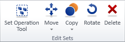
On the Home tab, the Edit sets group includes tools for moving, copying, rotating, and deleting model objects.
These tools can be used regardless of object type: you can, for example, delete pipe parts, duct parts, and structural parts at the same time. In some cases, also parts associated with the selected parts will get selected. For example, selecting an object that has an attached 3D Space will also select the 3D Space, unless you disable the Auto-select dependent (Alt+A) function.
About set commands and 3D spaces
If a model object has a 3D Space object attached to it, using these tools will affect both object types. For example, if the inspection hatch of an air duct has a Service Space in front of it, using the Delete tool selects both the duct part and the Service Space for deletion.
About set commands and Hull parts
Plant Modeller prevents piping designers from checking out and requesting ownership of hull parts. If the HullTools applet is installed and object's system ID is in the range [106, 112], then Plant Modeller considers the object to be a hull part. In situations where it is necessary to fix some problems related to hull parts, perform the following steps:
-
Run the script Diagnostics/AccessControlOfHullParts.mac and enable the access.
-
Perform the necessary operations to the hull parts: check out, delete, and so on.
-
Run the script Diagnostics/AccessControlOfHullParts.mac again and DISABLE the access. (If this is not performed, the hull parts remain accessible and there might be unwanted changes to them.)
Set operation tool

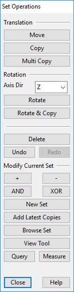
Select Home tab > Edit sets group > Set operation tool to open the Set Operations dialog, where you can perform various operations on a set of objects.
|
Command |
Description |
|---|---|
|
Translation |
|
|
Select Move to move the current object set to a different location. You are prompted to define a base point and then the new location. You can continue moving the same set multiple times. Press Enter or Esc to accept the location and return to the Set Operations tool. |
|
|
Select Copy to create one or more copies of the current object set. You are prompted to define a base point and then the new location. Each time you select a new location a new copy is added to that location. Press Esc to return to the Set Operations tool. |
|
|
Select Multi Copy to create one or more copies of the current object set at equal distances. You are first prompted to enter the number of copies to create, and then a base point and the new location. The same distance is applied between each copy. |
|
|
Rotation |
|
|
Select a rotation axis for Rotate and Rotate & Copy operations. This can be one of the main axes (X, Y, Z) or a user-defined axis. |
|
|
Select Rotate to rotate the current object set. First, define a point on the rotation axis. If Axis Dir is set to 'Define', you are asked to define a second point; otherwise, the axis is computed from the first point and the selected main axis direction. Then define the rotation angle counterclockwise around the axis. You can type the value or measure an angle between two 3D vectors digitized from the model. |
|
|
Select Rotate & Copy to create rotated copies of the current object set. This is otherwise the same as Rotate, but at the end you are prompted to enter the number of copies to be made. The same rotation is applied to each copy. |
|
|
Select Delete to delete the objects in the current object set. |
|
|
Select Undo to undo and Redo to redo set operations. |
|
|
Modify Current Set |
|
|
Select + to add objects to the current object set. |
|
|
Select - to remove objects from the current object set. |
|
|
Select AND to combine the current object set with another set using a Boolean AND. Example: Objects A and B are in the current set. You select objects A and C into another set. Result: Only A remains in the current set. |
|
|
Select XOR to combine the current object set with another set using a Boolean XOR. Example: Objects A and B are in the current set. You select objects A and C into another set. Result: Only B and C remain in the current set. |
|
|
Select New Set to clear the current object set and select a new set of objects. Press Enter to accept and return to the Set Operations tool. |
|
|
Select Add Latest Copies to add the most recent copies to the original set. Example: You want to create two rows of ten pillars.
|
|
|
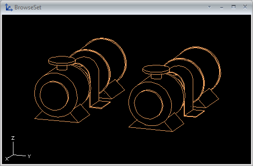
Select Browse Set to show the current object set in a separate BrowseSet view. Use the Set Browser dialog to control the display in the BrowseSet view. |
|
|
Select Measure to select a view and open the Set Properties of View dialog, where you can modify the view properties. |
|
|
Select Query to select an object and display its Object properties. |
|
|
Select Measure to measure distances in the 3D model. |
|

Move

You can move or move and rotate objects.
Move
You can move a set of model objects.
Do the following:
-
Select Home tab > Edit sets group > Move > Move.
-
Select the objects to be moved, and press Enter.
-
Pick a base point for the move.
-
Start moving the objects toward their intended location. You can also use these context-menu commands:
-
You can perform incremental moves with Accept point (Space, click) and undo moves with Undo (U).
-
You can change the base point with Set base point (B).
-
You can toggle the preview animation on or off with Show animation (Shift+K).
-
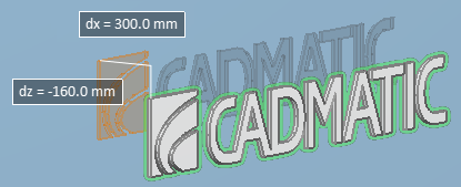
You can restrict cursor movements with the floating distance fields [dx = ] [dy = ] [dz = ]. You can toggle these input fields on or off with Use direction assistance (Shift+O) and activate them for editing with Ctrl+Tab. If you edit a distance value and press Enter, then that distance/direction becomes fixed and the objects can only move in directions that are not fixed.
-
You can restrict cursor movements by enabling Navigate > Ortho (F8). When ortho is enabled, the cursor can only move from the base point to one axis direction at a time.
-
-
Pick the new location for the base point.
-
Press Enter to complete the move.
Move and rotate
You can move and rotate a set of model objects.
Do the following:
-
Select Home tab > Edit sets group > Move > Move and rotate.
-
Select the objects to be moved and rotated, and press Enter.
-
Pick a base point for the operation.
-
Pick a new location for the base point.
-
Press Enter to accept the move.
-
Define the rotation axis:
-
Select a main axis by clicking the center of the selection wheel or using the Change rotation main axis (O) command.
-
Select a custom axis by pressing P and defining the axis direction using context-menu commands.
-
-
Define the amount of rotation:
-
Use the mouse or the arrow keys to rotate the objects.
-
Use the Enter rotation angle (Alt+R) command to type the rotation angle.
-
If moving a single object, use the Align to coordinate axes (Alt+A) command to align the object with the coordinate axes.
-
-
Press Enter to accept the rotation.
Copy
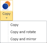
You can copy, copy and rotate, or copy and mirror objects.
If you copy a linked (sister project) object, the new copy is not linked to Sister Project Management.
Copy | Copy and rotate | Copy and mirror
Copy
You can create copies of existing model objects.
Do the following:
-
Select Home tab > Edit sets group > Copy > Copy.
-
Select the objects to be copied, and press Enter.
-
Pick a base point for the copying, and then start moving the objects.
Tip: You can enable Ortho (F8) to restrict the movement to horizontal and vertical directions.
-
To create more than one copy, select the command Number of copies (N) and specify how many copies to create.
-
Pick a new location for the base point.
-
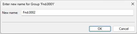
If the copied objects are members of a group that must have a unique name, the Enter new name for Group dialog opens. Select how to proceed.
 Show/hide details
-
To create a new group, enter a unique group name, and click OK.
-
To not assign the new objects into a group, click Cancel.
-
-
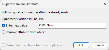
If the copied objects have attributes that must have a unique value, the Duplicate Unique Attribute dialog opens. Select how to proceed.
Show/hide details
-
To assign this attribute to the new object, enter a unique attribute value and click OK. The dialog re-opens for each additional attribute assignment.
-
To not assign this attribute to the new object, select Remove attribute from object and click OK.
-
To not assign this or any other attribute that still requires a unique value, select both Remove attribute from object and Remember my choice for other duplicates and click OK.
-
To cancel the copy operation, click Cancel.
-
-
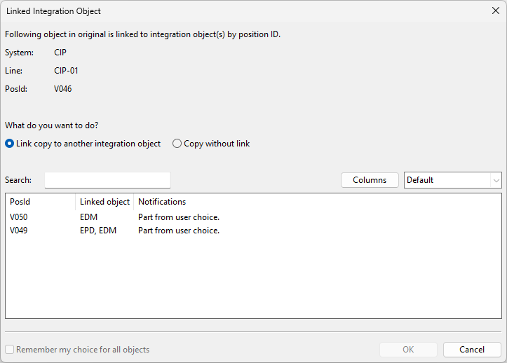
If a copied object is linked to an integration object via its position ID, the Linked Integration Object dialog opens, listing the integration objects whose position ID is still available.
Show/hide details
-
To link the new object to a different position ID, select the Link copy to another integration object option and one of the integration objects from the list, and then click OK.
-
To create the new object without position ID, select the Copy without link option and click OK.
-
Copy and rotate
You can create rotated copies of existing model objects.
Do the following:
-
Select Home tab > Edit sets group > Copy > Copy and rotate.
-
Select the objects to be copied and rotated, and press Enter.
-
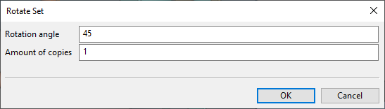
Pick the point around which to rotate the objects. The Rotate Set dialog opens.
-
Specify the rotation angle and the number of copies to be created, and click OK.
-
Define the rotation axis. For example:
-
Select a main axis by pressing X, Y or Z.
-
Define a custom axis by selecting the command Custom rotation axis (D) and using the on-screen tool and context-menu commands.
Then press Enter to accept the rotation.
-
-
If the copied objects are members of a group that must have a unique name, the Enter new name for Group dialog opens. Select how to proceed.
Show/hide details
-
To create a new group, enter a unique group name, and click OK.
-
To not assign the new objects into a group, click Cancel.
-
-
If the copied objects have attributes that must have a unique value, the Duplicate Unique Attribute dialog opens. Select how to proceed.
Show/hide details
-
To assign this attribute to the new object, enter a unique attribute value and click OK. The dialog re-opens for each additional attribute assignment.
-
To not assign this attribute to the new object, select Remove attribute from object and click OK.
-
To not assign this or any other attribute that still requires a unique value, select both Remove attribute from object and Remember my choice for other duplicates and click OK.
-
To cancel the copy operation, click Cancel.
-
-
If a copied object is linked to an integration object via its position ID, the Linked Integration Object dialog opens, listing the integration objects whose position ID is still available.
Show/hide details
-
To link the new object to a different position ID, select the Link copy to another integration object option and one of the integration objects from the list, and then click OK.
-
To create the new object without position ID, select the Copy without link option and click OK.
-
Copy and mirror
You can create mirrored copies of existing model objects.
Prerequisites
-
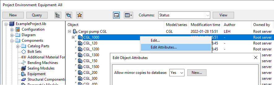
To mirror both the position and the geometry of a structural component or equipment, the component model (GDL) must have the attribute "Allow mirror copies to database" set to "Yes". If the GDL has parametric models, then the attribute must be in the parametric model that the model object is using.
If the attribute is missing or its value is "No", then this command only mirrors the position of the object but not its geometry, because mirroring the geometry would also require the component model to be copied and mirrored.
Note: You do not need to add the attribute to components that are symmetric along their axis.
Do the following:
-
Select Home tab > Edit sets group > Copy > Copy and mirror.
-
Select the objects to be copied and mirrored, and press Enter.
-
Pick a point for the mirror plane.
-
Define the direction of the mirror plane. For example:
-
Select a main axis for rotation by pressing X, Y or Z.
-
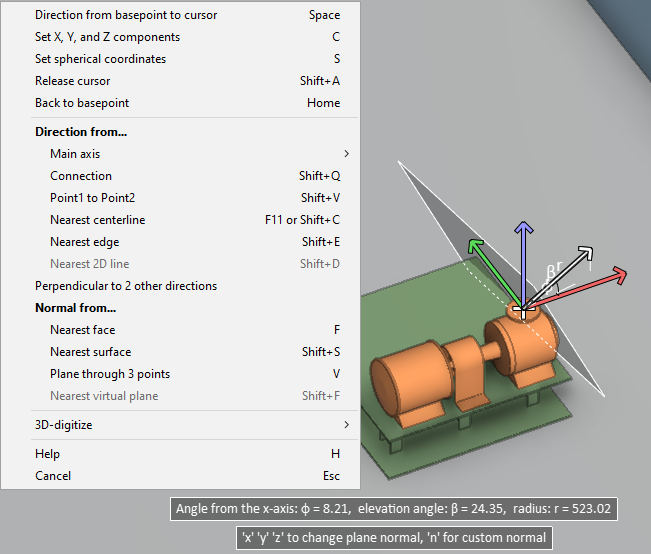
Define a custom axis by selecting the command Normal (N) and defining the plane direction using the on-screen tool and context-menu commands.
Then press Enter to accept the direction.
-
-
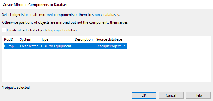
If you are copying a structural component or equipment whose component model has the attribute "Allow mirror copies to database" set to "Yes", the Create Mirrored Components to Database dialog opens.
For each object that is being copied, select how to proceed:
-
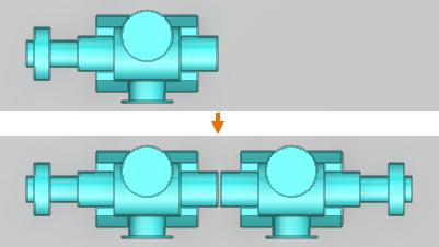
If you select the object from the list, both the position and the geometry are mirrored. This also copies and mirrors the component model, and the new object is linked to the new, mirrored component model.
The new component model is saved in the same database as the original component model (library or project), unless you select Create all selected objects to project database to add all the new component models to the project database.
-
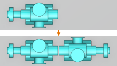
If you do not select the object from the list, only the position is mirrored, and both the old object and the new object are linked to the same component model.
Then click OK.
-
-
If the copied objects are members of a group that must have a unique name, the Enter new name for Group dialog opens. Select how to proceed.
Show/hide details
-
To create a new group, enter a unique group name, and click OK.
-
To not assign the new objects into a group, click Cancel.
-
-
If the copied objects have attributes that must have a unique value, the Duplicate Unique Attribute dialog opens. Select how to proceed.
Show/hide details
-
To assign this attribute to the new object, enter a unique attribute value and click OK. The dialog re-opens for each additional attribute assignment.
-
To not assign this attribute to the new object, select Remove attribute from object and click OK.
-
To not assign this or any other attribute that still requires a unique value, select both Remove attribute from object and Remember my choice for other duplicates and click OK.
-
To cancel the copy operation, click Cancel.
-
Rotate

You can rotate objects around a specified base point and axis.
Do the following:
-
Select Home tab > Edit sets group > Rotate.
-
Select the objects to be rotated, and press Enter.
-
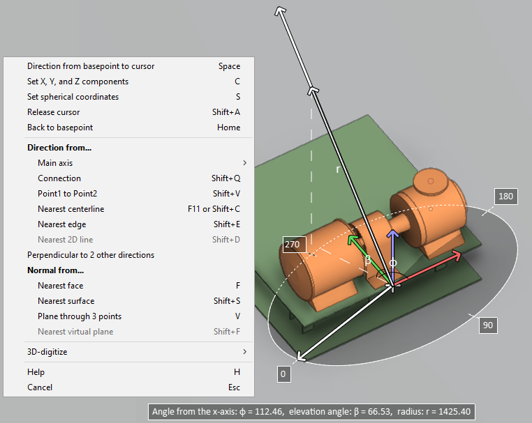
Pick a base point for the rotation. A selection wheel is displayed on the screen.
-
You can use the following context-menu commands to change the rotation axis:
-
Change rotation main axis (O) – Select a main axis for the rotation. (Same as clicking the center of the selection wheel.)
-
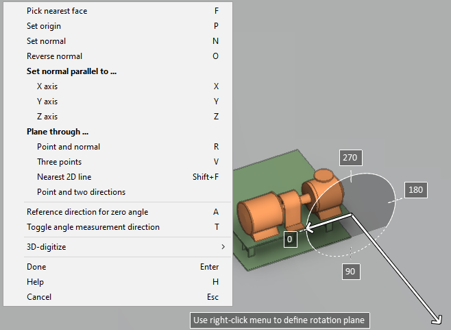
Define rotation plane (P) – Select a custom rotation axis by defining the axis direction with a suitable context-menu command.
-
-
You can use the following methods to define the amount of rotation:
-
Use the mouse to rotate and click to accept.
-
Use the arrow keys to rotate and the Space bar to accept.
-
Use the Enter rotation angle (Alt+R) command to type the rotation angle.
-
Use the Align to line (Alt+L) command to align the objects by first defining a base line with two points and then a target line with two points. You can use this, for example, to align a set of objects with the edge line of another object.
-
Use the Align to main axis (Alt+A) command to align the object with the main coordinate axes, if rotating a single object.
-
-
Press Enter to accept the current rotation as the final one.
Delete

You can delete model objects. When a deleted model object has a hole request, its state is set to To be deleted.
Do the following:
- Select Home tab > Edit sets group > Delete.
- Select the objects to delete, and press Enter.