Move Point
On the Piping tab, in the Pipe group, use the Move Point tools to move, shorten, or lengthen a pipe based on a selected connection point. However, note that you cannot use this tool to move a branch point; to move a branch, use the Slide branch command instead.
Moving a point does not add or remove parts. The length of straight parts changes, but their direction stays the same except when using Move point in curve, allow angle to change. The minimum length for a straight part is by default 10 mm—if using a bending machine, it might require a specific minimum length.
If using Connect (P) to move the point so that it connects to another pipe, the gasket gap is taken into account when the connection involves a gasket.
If the modified pipe has a hole request, the tools also try to update the location of the hole request.
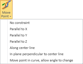
No constraint
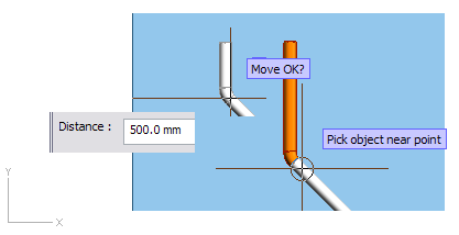
This method moves the point so that the direction is not locked.
Do the following:
-
On the Piping tab, in the Pipe group, select Move Point > No constraint.
-
Select a piping object by picking it near the connection point which you want to move, and accept the selection.
-
Define the new location, for example, using Connect (P), Set distance (D) or Set radius and angle (S).
-
Accept the new location.
-
Accept the move.
Parallel to X, Parallel to Y, Parallel to Z
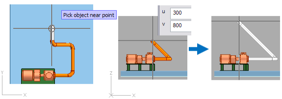
These methods enable moving the point in the positive or negative direction of the given main axis. You can use, for example, Set distance (D) to define the distance of the movement or Connect (P) to connect to another pipe.
In the example below, the point is moved parallel to the Y axis.
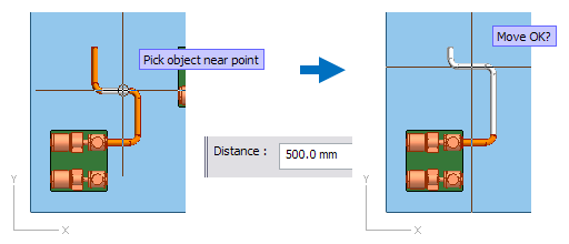
Along center line
This method enables moving the point along the centerline of the pipe, in positive or negative direction. You can use, for example, Set distance (D) to define the distance of the movement or Connect (P) to connect to another pipe.
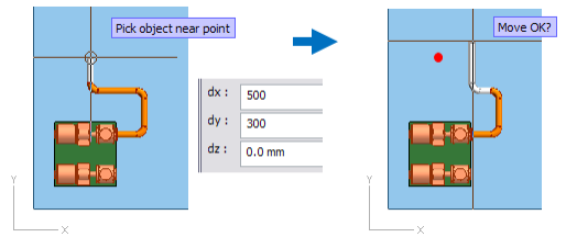
In plane perpendicular to center line
This method enables moving the point in a direction that is perpendicular to the centerline of the pipe. You can use, for example, Set distance (D) to define the distance of the movement or Connect (P) to connect to another pipe.
In the example below, the pipe is selected from a top view so the plane that is perpendicular to the centerline is parallel to the XZ plane. The distances are u=300 (along x axis) and v=800 (along z axis). The angle of the curves does not change, but the length of the straight pipes does.
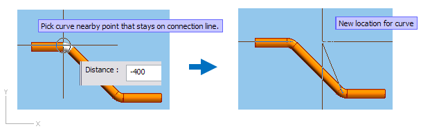
Move point in curve, allow angle to change
This method enables moving a curve along the centerline of the connected straight pipe. Unlike the other methods, this method can change the angle of the curves.
Consider the following restrictions:
-
After enabling the tool and picking the point to be moved, the cursor is constrained to move along the centerline of the connected pipe.
You can unlock the constraint by pressing Ctrl+A, but the new location will still be projected to the centerline.
-
The parts involved in this operation cannot have branches or onto-pipe parts connected to them.
-
The parts between the curves must be of the following geometry types:
-
DM_GT_PIPE
-
DM_GT_2P
-
DM_GT_VALVE
-
DM_GT_TEE
Note: If a T-piece has branches, they will not follow the T-piece to the new location.
-
- Bending machines can define a minimum length for a straight segment between two curves. If curves are bent by machine, trying to move a point to a location where the minimum distance would not be met prompts you to choose how to proceed.
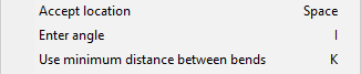
You can complete the move with the following commands:
- Accept location (Space) – Accepts the new location of the point.
- Enter angle (I) – Allows entering an opening angle (5–93) for the curve. The new location for the point is adjusted to comply with the specified angle.
- Use minimum distance between bends (K) – Ensures that the point does not violate the minimum straight distance that the bending machine requires between two curves.