Compare topology
Select Tools tab > External data group > Manage > Compare topology to select one or more P&I diagrams and compare the piping in the 3D model to the respective piping in the P&I diagrams. Then, the Topology Comparison Results dialog opens, listing any differences it might have found in the topology of systems, pipelines, and model objects.
Project administrators can also set topology comparison to be run as part of Isometric Check Results.
Topology Comparison Results
The Topology Comparison Results dialog shows the results of topology comparison.

The left pane displays the topological hierarchy of systems and pipelines that exist in the 3D model and in P&I diagrams, and the right pane lists the entities that are contained in the currently selected hierarchy level. Status icons show whether differences were detected and what is their severity. At hierarchy level the status is the same as the most severe status within the hierarchy.
-
 – OK
– OK -
 – Incomplete
 -
 – Conflict
In the Show menu, select what to show in the dialog:
- All – Show all objects.
- Differences only – Show only the objects that have differences. The possible differences are listed in Differences found in topology comparison.
In the result list, you can use the following context-menu commands:
-
Query object – Opens the Object properties dialog of the 3D model object.
-
Locate – Shows the 3D model object in a separate view.
-
Locate difference – Shows the location of the problem in a separate view. In the example below, a branch missing from the P&I diagram is causing a conflict, and the user can jump to that location in the 3D model.
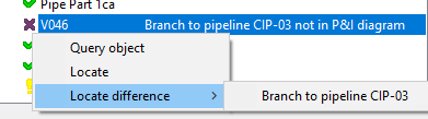
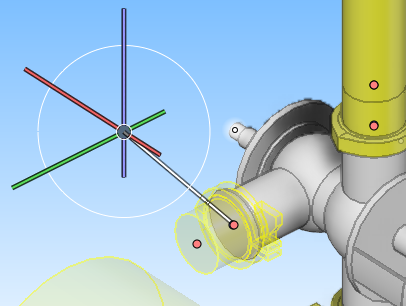
In some cases, the command can draw a rubber band line from the problematic object to the cursor, to pinpoint the exact location.
 Show/hide example
In this example, the nominal size of a node does not match and the rubber band line is drawn from the node.
Differences found in topology comparison
The following table lists the differences that the Topology Comparison Results dialog can report.
|
Level |
Status |
Differences message |
Reason |
|---|---|---|---|
|
Run |
|
Missing standard components with position id(s) |
A number of Standard Components with position ID are missing from the pipe run. |
|
Run |
|
Incomplete |
Pipe run is incomplete. |
|
Run |
|
Invalid Header /Tail connection to <name> |
Pipe run's head/tail connection to pipeline or Equipment identified by <name> does not match the connection in the P&I diagram. |
|
Object |
|
Missing from run |
Standard Component with position ID is missing from the 3D model pipe run. |
|
Object |
|
Not in model |
Standard Component or Equipment with position ID is missing from the 3D model. |
|
Object |
|
Not in P&I diagram |
Standard Component with position ID is not in any P&I diagram. |
|
Object |
|
Location should be after <name> |
Location of Standard Component with position ID in P&I diagram is after branch or Standard Component with position ID identified by <name>. |
|
Object |
|
Branch to pipeline <name1> should be after <name2> |
Location for branch to pipeline <name1> in the P&I diagram is after branch or Standard Component with position ID identified by <name2>. |
|
Object |
|
Branch to pipeline <name> not in P&I diagram |
Branch to pipeline <name> does not exist in the P&I diagram. |
|
Object |
|
Nominal size <ns1> should be <ns2> |
Piping part's nominal size <ns1> does not match the nominal size <ns2> in the P&I diagram. |
|
Object |
|
Nominal sizes in 3D model and network differ too much to confirm pipe run |
This means that the tool has detected that the nominal sizes in the 3D model do not fully correspond with the nominal sizes in the topology network created from the P&I diagram, but it is not able to pinpoint the exact location. This can be due to several reasons:
To solve the error, you can try the following:
Sometimes it can happen that the topology report simply cannot be sure of the pipe run direction and the error will remain, even though both the 3D model and the P&ID content are correct. This can be resulting from the design style or the location of the parts, for example, if reducers are drawn in P&ID or if pipe runs start from or end in nothing. |
|
Object |
|
Compartment <c1> should be <c2> |
Standard Component or Equipment is in compartment <c1>, but according to the P&I diagram it should be in compartment <c2>. |
|
Object |
|
Object should be connected to mapped node '<name>' |
Armature or Equipment is connected to a pipe run using some other node than the node (<name>) that has been mapped in the P&I diagram. See Mapping nodes between P&I diagram and the 3D model. |
Note: The position ID of a Standard Component is in the "Valve Position Id" attribute or in the "Instrument Position Id" attribute. The position ID of Equipment is in the "Equipment Position Id" attribute.
Generating a topology comparison report
In the Topology Comparison Results dialog, you can generate a topology comparison report.
Do the following:
-
Click Generate. The for report dialog opens.
-
Select "Topology report" (or a custom listing, if available) and click OK.
-
Enter a name for the report file (no spaces in the name), and click OK. The report is saved in your workspace, in <username>.wsp\<areaname>.pm\docu\.
Tip: Alternatively, you can export the contents of the difference pane to a Microsoft Excel file by pressing Ctrl+E.