Settings
Construction > Welds/Bevels > Settings
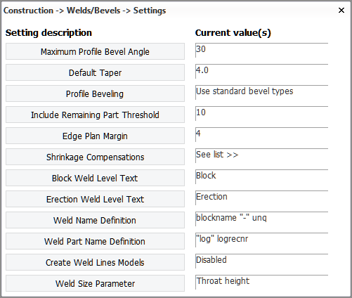
Maximum Profile Bevel Angle
Define the maximum angle that can be set for the bevel angle function for profiles. Values between 0 and 90 are valid.
Default Taper
Define the default taper value.
Profile Beveling
Select which bevel types are used for profile end types:
See also Modifying bevels and Adding bevels to profile end types and face plates in the Weld Management and Traceability Reference Guide.
Include Remaining Part Threshold
The automatic beveling function (Bevel Generator) adds bevels to plate relations with profiles, face plates and pillars in cross section. The bevel is placed at that part of the relation which is common with the plate border and the profile contour. When the relation between the plate and the profile is longer than the common part, the system extends the bevel by the length difference.
With this setting you can set the threshold for considering the length difference between the relation and the common part.
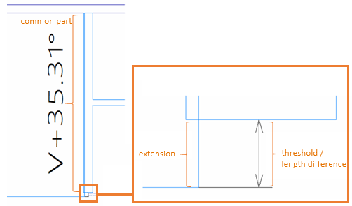
When the length difference is bigger than the threshold, the common part is not extended. This setting is valid for relations to (shell) plates in cross section, plates in plan view, profiles in cross section, and hull lines.
Edge Plan Margin
This setting is used in the automatic beveling of plate-to-profile and plate-to-plate connections to determine which bevel edge type to apply. It is a margin value for the distance between a plate and a related profile, or between a plate and related plate in cross section. The system uses the margin value as a threshold to change the bevel edge type. The edge type that is applied on a bevel depends on whether the distance between the related parts is within this margin or not (equal or smaller, or bigger). The default value is 4 mm.
-
For plate-to profile connections, the setting value is the distance in mm between the plate plane and the profile plane, or between the plate plane and the edge of the profile body or flange.
-
For plate-to-plate connections, the setting value is the distance in mm between the plate edges. Note that this setting applies to plates' relations to plates in cross section only.
For more information regarding plate-to profile connections, see Bevel edge types.
For more information regarding plate-to-plate connections, see Bevel edge types.
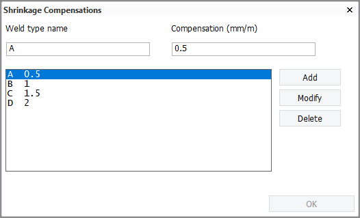
Shrinkage Compensations
Define shrinkage compensations for welds types.
Weld type name is the type shown as Weldtype in the Shrinkage Compensation menu when adding manual shrinkage compensation.
Compensation is the factor by which each profile having that weld type is compensated, expressed in mm/m per each profile on the plate.
Block Weld Level Text
Define the text that is applied to weld lines which belong to a block (block welds). The default value is Block. The maximum length of the text is 32 characters.
Erection Weld Level Text
Define the text that is applied to weld lines welded during an erection phase (erection welds). The default value is Erection. The maximum length of the text is 32 characters.
Weld Name Definition
Define the name of a weld. The available general keywords can be used along with the special keywords weld_method and unq. The weld_method keyword is replaced by the name of the weld method while generating the output. The keyword unq is replaced by a number generated by the system, which is unique within the block, while generating the weld lines.
Weld Part Name Definition
Define how a welded part is named. The available general keywords can be used.
Create Weld Lines Models
Enable or disable the creation of weld line models. The models are used to show weld lines in the WBD 3D sketches. The models are saved in the <block>\3dparts\welds folder, and named as log<logistical key>.mod. Each model file contains all the weld lines that belong to the part with that logistical key.
-
The weld lines are written to the model as polylines. The attribute information is as follows:
attribute 1: weldline
attribute 2: WTY=<bevel type>,WTM=<weld method>,LVL=<weld level>,WLOG=<logistical key of the welded part>,WTDB=<block number of the welded part>
attribute 3: CDB<block name>
attribute 4: <plate key> TDB <block number>
attribute 5: <attribute key> (or empty if not applicable)
attribute 6: <plate key of the welded part> TDB <block number of the welded part> (or empty if not applicable)
attribute 7: <attribute key of the welded part> (or empty if not applicable)
attribute 8: <logictical key> TDB <block number>
attribute 9: <GUID>
attribute 10: <plane equation (a,b,c and d from ax+by+cz=d)> <normal of the welded part> -
The attribute information is not updated if weld properties are changed in Weld Manager.
-
The weld models are not deleted if the part that they belong to is deleted.
Weld Size Parameter
Define which weld dimension property is shown in the Weld tab of the Bevel dialog when users insert or modify bevels, Throat height (default) or Leg length.
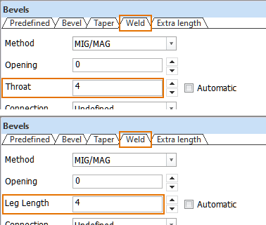
See Weld tab.