Automatic bevels for plate-to-profile relations
Bevels can be created automatically for plates related to profiles, pillars, face plates, and shell frames in plan view or in cross-section (bulb view). When determining the bevel types for these relations, the system uses beveling rules which are similar to the beveling rules for plate-to-plate relations. See Plate beveling rules.
The bevel is added to that part of the plate contour where the bevel connects with the other part, and according to the plate beveling rules.
The related profiles, pillars, shell frames and face plates can be straight or bent. In the case of bent parts, only the straight part is considered.
The following conditions must be met for adding bevels automatically:
-
The parts are really connected, that is, there is no distance between them.
-
No manual bevel has been placed at that part of the plate contour where it connects with the other part.
Connection types
The connection of the plate to a profile, pillar, face plate or shell frame is considered to be either:
-
A connection in plan view. The value for the connection variable in the plate beveling rules is bvl_conn_plt_plan.
-
A connection in cross-section. The value for the connection variable in the plate beveling rules is bvl_conn_plt_section.
Whether the connection type between the plate and the other part is considered to be a connection in plan view or a connection in cross-section varies depending on the situation. Generally speaking the relation is considered to be a connection in plan view when the plate is in line with the profile body, and a connection in cross-section when the plate is not in line with the profile body, or the plate is related to the profile flange.
The following help topics describe how the system determines the connection types for different related parts in different situations:
Beveling rules
The connection type determines which plate beveling rules are used.
A set of beveling rules for the two connection types are defined in separate bevel configuration files. The general predefined bevel rule defines which bevel configuration files contain these rule sets. The bevel configuration file for the general predefined bevel rule is pdbrule0000.cfg, located in the \norms\cvar\weld folder of the norms.
By default the bevel configuration file for connections in plan view is pdbrule0100.cfg, and pdbrule0200.cfg for connections in cross-section.
For detailed information on the plate beveling rules, see Plate beveling rules.
Bevel edge types
The edge_type variable can be used in plate beveling rules to determine which bevel edge type to apply in different situations, depending on how the plate is positioned to the related profile. This means that the bevel's edge type can be determined based on the connection type between the plate and the related part. There are three values for the bevel edge types, which are used for the different connection types. The edge type values are as follows:
-
EDGE_PLAN is used for connections to parts in plan view.
The edge type is EDGE_PLAN in cases where the plate plane is in line with the profile body, and always for squares, ducts, UNP profiles and H-bars (regardless if the connection is at the molded side or at the other side).
 Show/hide images
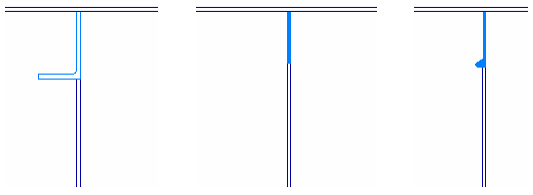
Plate plane in line with profile body
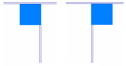
Connections to square profile, at both sides
-
EDGE_ANGLE is used for connections to parts in cross-section if there is an angle between the plate plane and the profile body or flange (more than one degree).
EDGE_ANGLE is also used if the plate stops at the edge of a flange.
Show/hide images
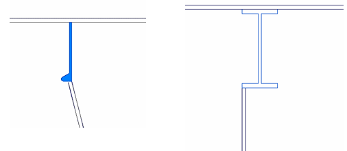
Left: Angle between the plate plane and the profile body
Right: Plate stops at the edge of flange
-
EDGE_STOP is used for connections to parts in cross-section.
For a pipe, axis or half round, the edge type is always EDGE_STOP.
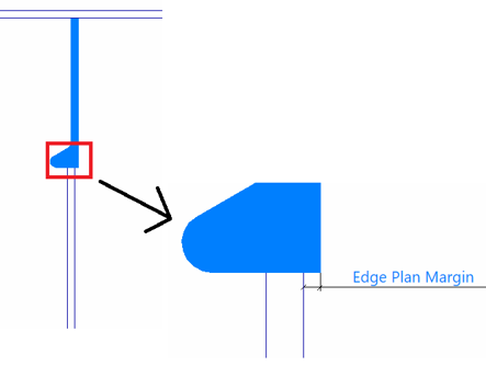
Edge Plan Margin
There can be some distance between the plate plane and the profile plane, or between the plate plane and the edge of the profile body or flange. The Edge Plan Margin setting in System Management > Construction > Welds/Bevels > Settings can be used to define which bevel edge type should be used on the bevel, depending on this distance. The value of this setting is a margin value that the system uses as a threshold to change the edge type that is applied to bevel. The edge type depends on whether the distance is within this margin value or not. The default value is 4 mm.
-
If the distance between the plate plane and the profile plane is equal or less than the margin value, the edge type is EDGE_PLAN. If the distance is more than the margin value, the edge type is EDGE_ANGLE.
Show/hide image
Distance between plate plane and profile plane
-
If the distance between the plate plane to the edge of the profile body or flange is equal or less than the margin value, the edge type is EDGE_ANGLE. If the distance is more than the margin value, the edge type is EDGE_STOP.
Show/hide image
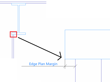
Distance between plate plane and flange edge
Automatic plate size adjustment
To prevent gaps and overlaps in the connection, the system automatically adjusts the plate size when there is an angle between the connected parts, taking into consideration the connection type and the bevel type.
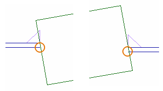
Left: Plate size adjusted to prevent a gap in the connection
Right: Plate size adjusted to prevent an overlap in the connection