Automatic bevels for plate-to-plate relations
Bevels can be created automatically according to plate beveling rules for the following plate-to-plate relations:
-
Plates related to plates in view
-
Plates related to plates in cross-section
-
Plates related to shell plates in cross-section
-
Plates related to the hull shape.
For information on the plate beveling rules, see Plate beveling rules.
Bevels are created automatically on plate relations which meet the following conditions:
-
The relation is to a hull line, to a (shell) plate in cross section, or to a plate in plan view.
Note: For relations to plates in cross section, automatic beveling only applies to complete and 1 vector relation types. Relations to plates in cross section which are of the end point relation type will not get automatic bevels. See Relation properties for information on the relation types.
-
The relation has some length on the contour.
-
No parallel distance has been added. This means that the second distance needs to be undefined and the first distance can be either undefined or equal to 0.
-
A knuckle must not be present at the location of the relation. The plates are connected with a knuckle on the left side of the image below, so no bevel can be created in this relation. On the right side of the image, the plates are not connected with a knuckle, so a bevel can be determined.

Only bevel types for bevels which are directly on the plate are determined when calculating the plate contour, and no bevels are added to the related plates in plan view. When using the Bevel Generator, also bevels on the related plates are defined.
Splitting a plate corresponds to creating, modifying or recalculating a plate. This means that after the splitting Bevel Generator should be used for creating all automatically defined bevels.
Note: Plate information, including logistic information, must be entered in the database prior to the determination of bevel types on relations to plates in cross section or to hull lines.
Note on shell plate thickness
In the case of a relation to a hull line, the thickness of the shell plate is usually unknown. Hull lines are applied in the same way that the Bevel Generator would calculate them.
System check on bevel changes
The system determines which bevels were changed by a CRC - Cyclic Redundancy Check. This helps boost performance since only the necessary computations are performed.
Bevel edge types
The edge_type variable can be used in plate beveling rules to determine which bevel edge type to apply between two plate edges, depending on how the plates are positioned relative to each other.
Possible values for the edge_type variable are:
-
EDGE_PLAN – Edge type to be used for plate connections to plates in plan view.
-
EDGE_ANGLE – Edge type to be used for connections to plates in cross-section when the plate edges are not in line (the edges are not on the same plane).
-
EDGE_STOP – Edge type to be used for connections to plates in cross-section when the plate edges are in line (the edges are on the same plane).
The edge_type variable can also be used for plate-to-profile connections. See Bevel edge types.
Edge Plan Margin
There can be some distance between the related plates' edges. For cases where a plate is related to a plate in cross section, the Edge Plan Margin setting in System Management > Construction > Welds/Bevels > Settings can be used to define which bevel edge type should be used on the bevel, depending on the distance between the plate edges. The value of this setting is a margin value that the system uses as a threshold to change the edge type that is applied to the bevel. The edge type depends on whether the distance between the edges of the plates is within the margin or not. The default value is 4 mm.
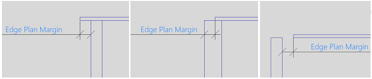
-
If the distance between the plate edges is equal or smaller than the set value, the edge type is EDGE_ANGLE.
-
If the distance between the plate edges is more than the set value, the edge type is EDGE_STOP.
Plate contour handling
The system handles the plate contour as follows.
Simplified definition of plate contour for relations to plates in cross section
The definition of the plate contour has been simplified for relations to plates in cross-section. Refer to Relation properties for more information.
Calculation of the plate contour for different bevel types
When a plate is related to another plate, its contour is calculated depending on the bevel type and the angle of the relation. Bevels are always viewed in next direction, depending on the nearest orthogonal direction:
- Downward
- Forward
- Toward the center line
Dimensions of a bevel can depend on the thickness of the plate they are placed on.
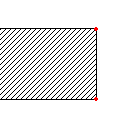
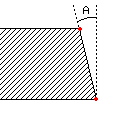
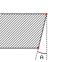
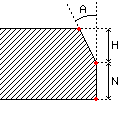
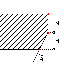
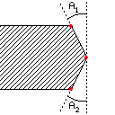
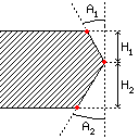
In the table below you can see an overview of all nine bevel types (see Bevel types), including the possible candidates to use when computing the plate contour. The red dots indicate the positions which are the correct candidates for different relations. Select those candidates that define the minimal relation to a plate in cross-section or hull line. In some positions, the relation needs some extension to preserve its correct length after beveling. The bevels in the table below are defined looking downward.
| Nr. | Type | Picture | Notes |
|---|---|---|---|
| 1. | I |
|
Candidates at molded and thickness side |
| 2. | V+ |
|
Candidates at molded and thickness side. Extension at top side: tan(A)*thickness |
| 3. | V- |
|
Candidates at molded and thickness side. Extension at lower side: tan(A)*thickness |
| 4. | Y+ |
|
3 candidates:
|
| 5. | Y- |
|
3 candidates:
Extension at lower side: tan(A)*H |
| 6. | X |
|
3 candidates:
Extension at top side: tan(A1)*thickness*0.5 Extension at lower side: tan(A2)*thickness*0.5 |
| 7. | X+ |

|
3 candidates:
Extension at top side: tan(A1)*H1 Extension at lower side: tan(A2)*H2 |
| 8. | X- |
|
3 candidates:
Extension at top side: tan(A1)*H1 Extension at lower side: tan(A2)*H2 |
| 9. | K |
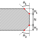
|
4 candidates:
Extension at top side: tan(A1)*H1 Extension at lower side: tan(A2)*H2 |
Computation of optimal plate contour by taking the bevels into account
Relations to plates in cross section or to hull lines can have bevels too. If this is the case and the relation touches that plate or hull line, the system will take the shift and extension of the bevel into account.
Relation to plate in cross section
When the plate touches another plate in cross section, the system calculates the contour based on the first bevel connected to this relation and also adds an extension when necessary See Calculation of the plate contour for different bevel types above. In case no bevel is found, then the I-bevel will be applied.
If the other plate is also related to the plate we are calculating the contour of, then an extra extension is added in the same way as if the plate had a maximal relation to the other plate.
If the relation has some distance to the plate in cross section, the calculation will remain the same.
Relation to hull line
Relations to the hull line can have a bevel too. If the relation touches the hull line, then the bevel is used in the calculation of the relation. If there is no bevel, an I-bevel is used.
Defining process codes for production
The process and job codes for parts can be added to the logistical database with the Production > Logistics > Process Codes function in the 3D-Contek and Shell applications. See Processing codes for parts for an overview.
The codes are defined in the setting groups in the Logistics > Process and Job Codes settings in the system Management application. See Process code and job code for details.
Process and job codes can be set for the following construction items:
- Plate
- Bracket
- Shell frame
- Profile type
- Lug
- Flange
- Knuckle
- Corrugated stiffener
- Bevel
- Taper