Levels
Production > Work Breakdown Structure > Levels
Define the work breakdown (WBD) structure. The work breakdown structure is used for creating Work Breakdown 3D Sketches and in Hull Viewer.
The WBD structure uses the logistical fields defined in the Logistical Database Layout as the levels. In the Levels dialog, the levels are order from the top level down to the lowest level. Each level represents a step in the assembly process.
Four levels have been pre-defined by default: Block–Sectionnumber, Panel–Panelname, SubPanel–PanelExtension and Part–Partnumber.
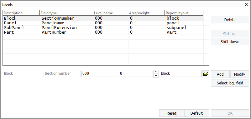
Levels can be added and deleted, and the order of the levels can be changed. The maximum number of levels is 16.
Adding, modifying and deleting WBD levels
Important: Clicking Reset will delete all defined WBD levels.
Adding levels
To add a new WBD level, do the following.
-
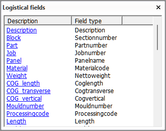
Click Select log. field, and select the desired logistical field from the list that opens.
-
This will fill in the Description and Field type fields.
Level name will be 000 and Area/weight will be 0 automatically. You can enter different values if needed. See Available fields below.
You can close the Logistical fields dialog by clicking the cross at the top right corner.
-
Click the Open folder icon to select the report layout to be used for this level. By default a report layout by the same name as the Description is used.
-
Click Add. The new level appears as the last level.
-
If necessary, move the new level up to the desired position by clicking Shift up.
-
Click OK to close the Levels dialog.
Modifying levels
To modify an existingWBD level, do the following.
-
Select the level that you want to modify.
-
Click Select log. field, and select the desired logistical field from the list that opens.
-
Change the Level name and Area/weight if so desired by enering new values.
-
Click Modify.
-
Click OK to close the Levels dialog.
You can move levels up or down clicking Shift up or Shift down.
Deleting levels
To delete a WBD level, do the following.
-
Select the level that you want to modify.
-
Click Delete.
-
Click OK to close the Levels dialog.
Available fields
Description and field type
The first two fields Description and Field type come from the logistical database layout.
-
Description is a unique descriptive name of the logistical database field as defined in the logistical datase layout.
-
Field type is the logistical database field type. This the "answer" to the Description field. For example, for Block, the answer is the block number or name.
Level name
Defines if a WBD level will be skipped when WBD sketches are generated, depending on the Description/Fieldtype value. WBD sketches will not be generated for the parts in the skipped WBD level.
For example, if 012 is set as the Level name value for the Block/Sectionnumber level, parts in block number 012 (which have 012 as the Block/Sectionnumber value) will not get WBD sketches. With the default value 000 in the default WBD structure, no WBD levels will be skipped.
All levels will be visible in the tree structure in Hull Viewer.
Area/weight
Defines if some parts in WBD skeches will not get a label.
Parts in the WBD branch which have a weight smaller than the value defined here will not get a label in WBD sketches.
If the Area logistical field is defined in the logistical database layout, parts which have a smaller area value than defined here will not get a label.
Report layout
If a report layout is selected for a WBD level, a part table will be present in the WBD sketches for that level. Report layouts are defined in Production > Reports > Report Layout, and stored in the report subfolder of the project's norms folder.
Note: Each level for which a part table is required must have a report layout defined. Without a report layout there will be no part table.
The table in each WBD level sketch will contain data for all the WBD levels below it. This means that the table of the top level has part information for all the levels below it (Panel, SubPanel and Part), and the table in the second lowest level sketch table has part information only for the lowest level (Part).
Consider the following when creating report layouts for WBD 3D sketches:
-
Each WBD level must have a column in the report layout. By default the levels are, from top to down, Block, Panel, SubPanel and Part. If other levels are defined for the WBD structure, a column must be added for each of them in the report layout. The columns are defined in the Detail settings of the report layout.
-
All columns for WBD levels must have the same column width in the same report layout, because the columns will be combined in the table. Different report layouts can have different column widths. The column width is set in the field format editor. Click the Edit field formats button in the Header settings of the report layout to open the field format editor, and set the desired Width for the fields that are used for the WBD levels.
-
Because the columns will be combined in the table, it is recommended that all columns which are for WBD levels have a matching header name. The header name can be any word, "Level" or "Item" for example. The header names for the columns are defined in the Header settings of the report layout.
- The header must have the same column separators at the same positions as set in Separator in the Detail settings of the report layout.
- The Assemblyorder logistical data field can be helpful to place the parts in the table according to the assembly order. Use the Assemblyorder field as the first field in the Footer settings of the report layout.
- The Lines per Page value in the General settings should be a fairly large number (550, for example) to avoid several headers in one table.
- Set Group lines in the General settings to zero to avoid empty lines in the table.
See Production > Assembly Sketch > Sketch Layout for information on the overall sketch layout.