Creating Profiles
Do the following to create profiles in the 3D-Contek application.
-
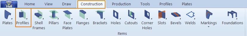
Select Construction > Profiles.
-
In the Insert group of the Profiles ribbon, select from the following profile creating functions:
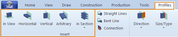
- in View – Create profiles in view (at plates in section of drawn blocks), pillar-profiles in view (at plates in section of dashed blocks), or shell frames (at hull lines) in view.
- Horizontal – Create horizontal profiles, relative to the active view.
- Vertical – Create vertical profiles, relative to the active view.
- Arbitrary – Create arbitrary profiles.
- in Section > Profiles in Section – Add profiles to plates in cross section.
-
in Section > Profiles in Section as Property – Add profiles to plates in cross section as plate properties instead of as actual profiles.
-
Selecting one of these options opens a dialog where you can define the following attributes:
- type of the profile
- whether the body and flange of the profile should be coded separately (composite profile)
- relations of the profile to fixed values or construction items
- number of profiles to create
- body size and thickness
- body direction and thickness direction
- molded side position
- material
-
After entering the necessary information, in the next dialog you can to define further limitations and end types.
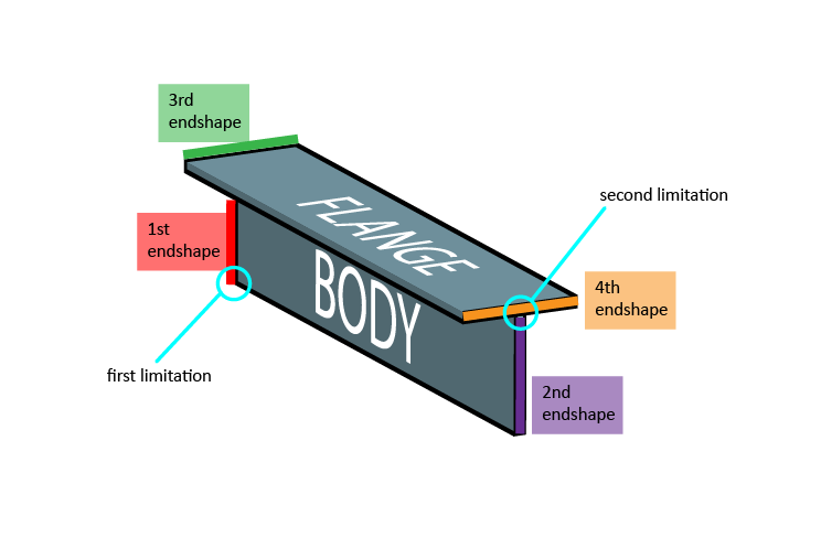
Generally speaking a profile can be given four end shapes:
- The first and second end shapes are used for the body of the profile
- The third and fourth end shapes are meant for the flange of the profile
Specifying the Limitations
After specifying the first limitation (lower end) of the profile, you proceed to determine the second limitation (the upper end) of the profile. The option in the dialog box automatically changes from First limitation to Second limitation.
Note: Different sets of endshapes can be defined for the 1st and 2nd and for the 3rd and 4th endshapes ,as not every combination of 1st and 3rd or 2nd and 4th endshapes is possible or desirable. The system administrator has the option to exclude certain combinations by adding label 6 in the type macro of an endshape in the norms folder. In this label one can define the possible 1st and 2nd endshapes that should be enabled, if the type's endshape is used as a 3rd or 4th endshape. For more information about type files read chapter The Type File and its subchapters.
-
Click OK to approve your profile. The profile will appear in the graphical window.
As options offered by the dialog box slightly differs in case of in view / arbitrary / horizontal / and vertical profiles, we recommend that you read the detailed description on these four profile types in the following chapters:
Topological Profiles
Profiles are constructed in topological relation to other construction items.
The position of the profile is defined by its start and endpoint. These points lie on a plate and can be related to other construction parts. Plates, profiles brackets, webframes, hull lines, yellow menu lines can be used as relations. In most cases each end will be described by the intersection of two relations. However, an end point can also be described by one or three relations.
The sub-chapters about creating profiles are also applicable for pillars, with the only difference that profiles are attached to plates while pillars are not.
To see some examples about topological relations of profiles, go to chapter Examples on Profile Relations.
For information on applying bevels to profiles and pillars, see Inserting and Modifying Bevels.
Relating profiles to grid values
Profiles can be related to user defined grid values so that if grid value change, the related profiles change along with them.
It is possible to work with decimal grid values and offsets at the same time, so a width value like 3.5B+10.5 is possible and is interpreted as 10.5 mm past the width value halfway grid 3 and 4. If width grid numbers 3 and 4 are set to 900 and 1200 mm respectively, then the previous example will evaluate to 0.5*(900+1200)+10.5=1060.5 mm.
Note that 3.5B+10.5 is not the same as 3B+160.5. With the current values for B3 and B4 there is no difference, but if B4 were to be moved to 1000 mm, then the first notation would be interpreted as 0.5*(900+1000)+10.5=960.5, while the notation 3B+160.5 would still yield 1060.5 mm.