Creating face plates
Face plates can be created in the 3D-Contek application of CADMATIC Hull. You can create face plates on plates and in holes.
To create face plates, go to Construction > Face Plates. Select the desired function from the Insert group.
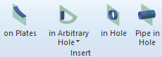
- Creating face plates on plates
- Creating face plates in arbitrary holes
- Creating face plates in holes
- Creating pipes in holes
Creating face plates on plates
Face plates can be created on a single plate and also on multiple plates. See Face plates on multiple plates below for information on the multiple plate case.
-
Indicate the plate in the graphical window. Click outside the plate, on the side where you want to attach the face plate. This plate will be the main plate in case the face plate is attached to multiple plates. The Face plate dialog opens.
-
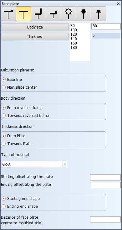
Select the face plate type from the options shown at the top of the dialog.
-
Select the face plate properties:
- Body Size and Thickness – Select from the predefined values, or enter the values in boxes on the right.
- Calculation plane at – Select the plane used for the calculation of the face plate contour, either Base line (default) or Main plate center. See Calculation plane below for more information.
- Body direction – Either from or towards the reversed frame.
- Thickness direction – Either from or towards the plate.
- Type of material – Select from the available options.
- Starting offset along the plate and Ending offset along the plate – Set the offsets for the start and end of the face plate along the plate contour. If negative, the face plate will be lengthened.
- Distance of face plate centre to moulded side – Enter the distance from the face plate centre to the moulded side of the (main) plate.
-
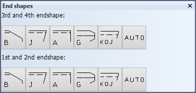
In the End shapes dialog, first select the 3rd and 1st endshape, and then the 4th and 2nd endshape.
-
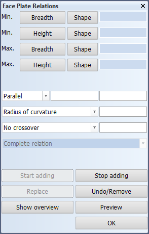
Next, the Face Plate Relations dialog opens. Indicate the relations in the graphical window. When you indicate the face plate relations, always click outside of the plate.
You can also enter the Min. and Max. limitation values (border values) for the relations in the dialog. For detailed information on how to indicate the relations in the graphical window, see Indicating face plate relations in plan view.
Note: If the 1st and 3rd relations are fixed value relations, the 2nd relation is to the main plate, and there are two or more intersection points with the 2nd relation and the 1st and 3rd relations, the relations must be defined in the order that follows the main plate contour direction. See Special case: multiple intersections with plate and fixed value relations for more information.
Functions in the dialog:
- Start adding – Continue selecting relations. Click this if you want to select more relations after modifying already selected relations.
- Stop adding – Stop selecting relations. Click this if you want to make changes to already selected relations.
- Replace – Replace the selected relation with another relation. Select the new relation or enter a fixed limitation.
- Undo/Remove – Undo the last added relation (when relations are being added) or remove the selected relation (when all the relations have been selected).
- Show overview – Display a list of all relations. Click again to close the list.
- Preview – Apply the changes and see the effect in the graphical window.
-
To apply the changes and close the dialog, click OK.
Face plates on multiple plates
In case a face plate is attached to multiple plates, one of the plates is the main plate that the face plate belongs to. When the main plate is recalculated, the face plate will be recalculated as well. The other plate(s) can be recalculated independently. If the main plate is deleted, the face plate gets deleted as well. If the other plates are deleted, the face plate will remain connected to the main plate.
Note that all the plates must be selected as relations to the face plate, or the production information will not be correct.
- Indicate the main plate.
- Select the face plate type, properties and endshapes.
- Indicate the face plate relations. All the plates that the face plate is to be attached to must be included.
You can later change the main plate, if necessary, in Construction > Face Plates > Modify > Main Plate.
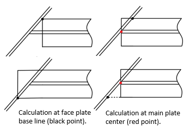
Calculation plane
The Calculation plane at setting allows you to set the plane that the system uses when calculating the contour of the face plate.
- When Base line is selected, the plane at the face plate base line, parallel to the main plate, is used as the calculation plane.
- When Main plate center is selected, the center of the main plate is used as the calculation plane.
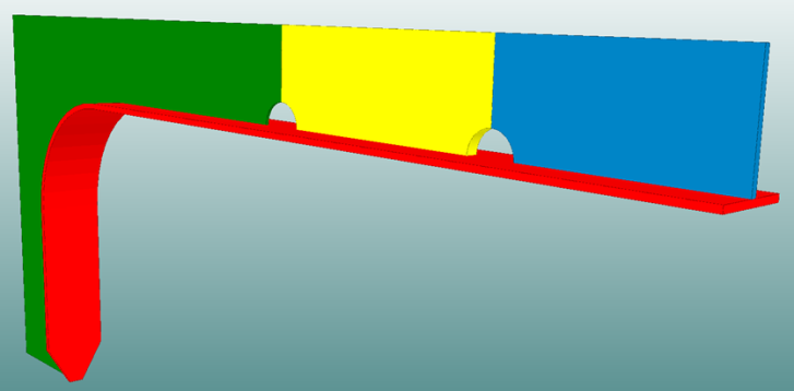
The face plate base line is at the molded side of the face plate, and goes parallel to the main plate plane.
In the images below, the base lines are marked with blue lines and blue dots.
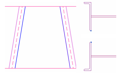
With some face plate end types, using the face plate base line as the calculation plane could cause a gap between the face plate and the plate. This gap can be avoided by using the plane at the main plate center as the calculation plane. The image below illustrates the two options with different body directions. Note how changing the body direction does not solve the gap problem when the face plate contour is calculated at its base line plane.
The calculation plane can be changed later with the Construction > Items > Face Plates > Modify > Direction function in the 3D-Contek application.
Creating face plates in arbitrary holes
Face plates in arbitrary holes can be bent or straight. Select from the following:
- Bent Face Plate in Arbitrary hole
- Straight Face Plate in Arbitrary hole
In the graphical window, indicate the side of the arbitrary hole where you want to place the bent or straight face plate. The Create Bent/Straight Face Plate dialog opens.
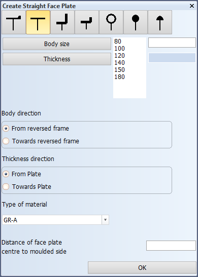
Define the following face plate properties:
- Select the face plate type from the options shown at the top.
- Body Size and Thickness – Select from the predefined values, or enter the values in boxes on the right.
- Body direction – Either from or towards the reversed frame.
- Thickness direction – Either from or towards the plate.
- Type of material – Select from the available options.
- Distance of face plate centre to moulded side – Enter the distance from the face plate centre to the moulded side of the plate.
Creating face plates in holes
One, two, or four face plates can be created in a standard hole.
Face plates can also be added to accepted requests for holes (RFHs) in projects linked to CADMATIC Outfitting, provided that the holes were created as standard hole types. The holes must be connected to the active block. See Face plates on hole requests for more information.
First select the holes where you want to place face plates in the graphical window. Use the options in the Hole Selection Menu dialog as necessary.
Click OK to open the Face Plate in Hole dialog.
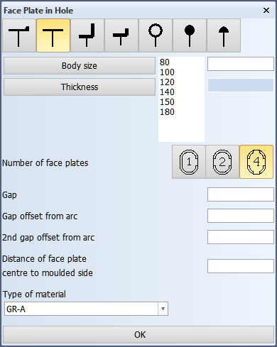
Define the following face plate properties:
-
Select the face plate type from the options shown at the top.
-
Body Size and Thickness – Select from the predefined values, or enter the values in boxes on the right.
-
Number of face plates – Select how many face plates to create in the hole.
-
Gap – Enter the gap size between two face plates.
-
Gap offset from arc – This value affects the position of the gaps between two face plates. In case 4 face plates are created, this setting affects only the vertical gaps (gaps in height). By default the gap position is at the center line of the longest side of the hole, except for door holes which have the default gap at the center line of the shortest side of the hole.
Enter the desired offset value in mm. The value is the distance from the starting point of the arc segment of the hole to the end shape of the face plate, along the straight segment of the hole. The gap on the other side (opposite side) moves symmetrically in the negative (opposite) direction.
-
2nd gap offset from arc – This value affects the position of the horizontal gaps (gaps in width) between two face plates when 4 face plates are created. It cannot be set if there are 1 or 2 face plates. By default the gap position is at the vertical center line of the hole.
Enter the desired offset value in mm. The value is the distance from the starting point of the arc segment of the hole to the end shape of the face plate, along the straight segment of the hole. The gap on the other side (opposite side) moves symmetrically in the negative (opposite) direction.
-
Distance of the face plate centre to moulded side – Enter the distance from the face plate centre to the moulded side of the plate.
-
Type of material – Select from the available options.
Click OK to create the face plate(s).
Notes on the gap offsets
Default gap offsets
A default value affecting both of the gap offsets can be set with the Minimum Bending Clamp Distance setting in System Management > Construction > Face Plates/Flanges > Settings. The value set in Minimum Bending Clamp Distance will be prefilled in both of the gap offset fields.
Effect of hole modification
When a hole which has face plates is modified, the system does the following:
-
If the size of hole is changed, the system recalculates the face plates.
-
If the hole type is changed from one standard hole type to another standard hole type, the system recalculates the face plates.
-
If the hole type is changed from a standard hole type to a user-defined hole type, the system removes the face plates.
Creating pipes in holes
First select the hole(s) where you want to place a pipe in the graphical window. Use the options in the Hole selection menu dialog as necessary. If you select more than one hole, the holes must have the same diameter. Click OK to open the Pipe in Hole dialog.
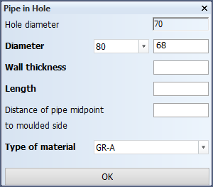
The diameter of the selected hole(s) is shown at the top.
- Diameter – Select from the predefined pipe diameters from the drop-down menu the left, or enter the pipe diameter in the box on the right.
- Wall thickness – Enter the wall thickness of the pipe.
- Length – Enter the length of the pipe.
- Distance of pipe midpoint to moulded side – Enter the distance from the pipe midpoint to the moulded side of the plate.
Click OK to create the pipe.