Export settings configuration
The Weld Manager export settings consist of the keywords listed below. Each keywords must be present in one of the two configuration files as described below. The keywords can be added manually to the configuration files, or defined with the corresponding settings in the System Management application.
| Keyword | Explanation | Configuration file | System Management setting |
|---|---|---|---|
| outfile | File name for the exported file. The usual keywords, including those found in Logistics > Logistical Field Options, can be used. See Logistical Fields Options. | %ncgnorms%\cvar\weld\weldmgr.cfg | Output Filename 1 |
| outformat |
Output format for the export. The following values are supported:
|
%ncgnorms%\cvar\weld\weldmgr.cfg | Output Format 1 |
| outpath |
Output directory for the export file. The usual keywords, including those found in Logistics > Logistical Field Options, can be used. See Logistical Fields Options. Note that the path must be enclosed in double quotes when added manually to the configuration file. |
%ncgnorms%\lvar\weld\weldmgrlocals.cfg |
Output Directory 1 |
|
processsinglewelds |
This keyword can be added to the weld configuration file with the value of no to prevent Single status welds from appearing in drawings, item information and weld reports. This keyword must be added manually to the weld configuration file. See Single and matched welds for more information. |
%ncgnorms%\cvar\weld\weldmgr.cfg |
No associated setting |
| weldgroup | Specifies which weld group data fields to include in weld reports. | %ncgnorms%\cvar\weld\weldmgr.cfg | Weld Group 1 |
| weldname | Specifies the the weld name. The usual general keywords can be used along with the special keywords weld_method and unq. The weld_method keyword is replaced by the name of the weld method in the output. The keyword unq is replaced by a number generated by the system, which is unique within the blocks. All of these keywords can be manipulated using the formatting feature, also known as the Field Format Editor in System Management Tools > Field Format Editor. | %ncgnorms%\cvar\weld\weldmgr.cfg | Weld Name Definition 2 |
| weldpartname | Specifies how a part should be named. The usual keywords, including those found in Logistics > Logistical Field Options, can be used. See Logistical Fields Options. | %ncgnorms%\cvar\weld\weldmgr.cfg | Weld Part Name Definition 2 |
| xlstemplate | Name of an Excel file to be used as a template for the Excel output, including the file path. | %ncgnorms%\lvar\weld\weldmgrlocals.cfg | Excel Template 1 |
|
1) In settings group Import/Export > Weld Manager. 2) In settings group Construction > Welds&Bevels > Settings. |
|||
See also Variables (keywords) in weld configuration files.
Export type Wiscon
This output consists of a customized XML file accompanied by a STEP file.
Export type Excel
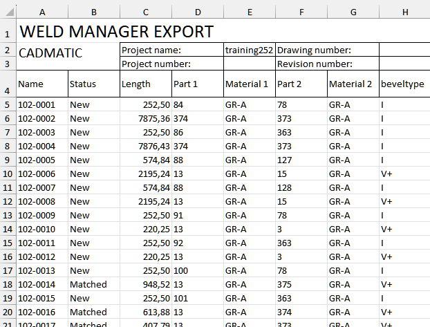
When the output format is set to be an Excel file, the export result for Weld Manager is an Excel file which contains all the weld lines within the block. The table can be customized by editing the template file (see below).
The output format can be set with the outformat keyword in the weld\weldmgr.cfg file in the current norms, or with the Output Format setting in System Management > Import/Export > Weld Manager.
Excel template file
The Excel file specified by the xlstemplate keyword in the %ncgnorms%\lvar\weld\weldmgrlocals.cfg file in the current norms is used as the template for the exported Excel file. It defines both the header part and the content of the columns below the header in the Excel report. The template file can also be specified with the Excel Template setting in System Management > Import/Export > Weld Manager.
Important: The template file must be of type XLS, not XLSX.
The template file consists of the header part containing general information, and the last row containing the data for each weld line.
Header part
All of the cells in the template, except for those on the last row, are considered to be part of the header.
-
Cells in the header section that do not have a comment are copied as such to the header of the exported weld report XLSX file.
-
You can use general keywords like projectname, object and currentdate in the header section. The system uses the value of those keywords in the exported weld report. The template's cell formatting is used in the report. Therefore the cells in the template should not be blank but contain example data in the proper intended format like Text, Number or Date.
Last row
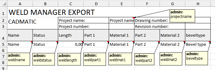
The last row in the template defines the content of the cells in the export. Cell contents are resolved values of the keywords contained in the cell comments.
Note: The template's cell formatting is used in the report. Therefore the cells in the template should not be blank but contain example data in the intended format like text, number or date.
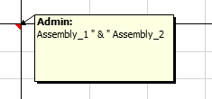
All logistical fields in the logistical database, including manually added logistical fields, can be used as keywords in the comments. Because a weld line connects two parts, you should add a postfix _1 or _2 to the logistical fields in the comments to indicate whether the keyword is for a part that has the weld, or a part that gets welded to the other part.
-
Postfix _1 indicates that the variable is for a part that the weld belongs to (first part).
-
Postfix _2 indicates that the variable is for a part that gets connected to the first part (second part).
Keywords
The system recognizes the following additional keywords:
-
attrecnr – The attribute key
-
bevelcode – A freely chosen one-character code for the bevel type, defined in Weld Codes, Third Part in System Management > Construction > Welds/Bevels > Weld Codes . The description is defined in the In drawing field of the dialog for each bevel type.
-
beveltype – The bevel type as hard-coded in the system (standard bevels I, V+, V−, X, X+, X−, Y+, Y− and K)
-
blockname_1 – The name of the block that the weld is located in
-
blockname_2 – The name of the block that the welded part is located in
-
blocknumber_1 – The number of the block that the weld is located in
-
blocknumber_2 – The number of the block that the welded part is located in
-
compartments – A list of Outfitting compartments that the weld crosses. See Compartment information in welds
-
compensation – The shrinkage compensation as defined in bevel properties
-
cons_angle – The angle between welded parts in degrees
-
edge_type – The edge type of the bevel where the weld is. One of the following: Undefined (should not occur), Single, Planar, Angle, Stopping, Hull, Seam, Hole, Curve (obsolete), Profile, Slot, Splitter, Faceplate, Parallel Unknown (should not occur).
-
extra_length – The extra length as defined in bevel properties
-
logrecnr – The logistical key
-
lower_angle – The lower bevel angle
-
lower_height – The lower bevel height
-
nose_height – The bevel nose height
-
opening – The bevel opening
-
pdb_number – The number of the used predefined bevel, 0 for custom bevels
-
pdb_name – The name of the used predefined bevel, empty for custom bevels
-
pdb_description – The description of the used predefined bevel, empty for custom bevels
-
placement – Manual or Automatic, depending on how the bevel was created
-
platerecnr – The plate key
-
unq – Replaced by a number generated by the system to make the weld name unique within the block. See Weld Name Definition.
-
upper_angle – The upper bevel angle
-
upper_height – The upper bevel height
-
wbdbranch#_1 – The work breakdown branch value of the first part, i.e. the part that the weld belongs to. Note that this keyword is not suppoted by HCA (Hull COS Agent) and thus not available for assembling weld attributes to send to CADMATIC Outfitting.
-
wbdbranch#_2 – The work breakdown branch value of the second part, i.e. the part that gets connected to the first part. Note that this keyword is not suppoted by HCA (Hull COS Agent) and thus not available for assembling weld attributes to send to CADMATIC Outfitting.
-
weld_factor – The throat height divided by the thickness of the thinner of the welded parts
-
weld_orientation – The orientation of the weld. One of the following:
-
Horizontal for welds on fixed height
-
Vertical for welds that have both fixed length and fixed width
-
Other for all other cases
-
-
weldatt* – Content of the weld attribute as defined by the corresponding att*, where * represents the attribute number (1–32). These attributes are set in System Management > Construction > Welds/Bevels >Weld Attributes.
-
weldcode – The weld code including the first, second and third part of the weld code (XX.XX.X). The parts represent the weld connection type, weld method and weld type, respectively. See Weld Codes.
-
weldconnect – The first part of the weld code (connection type). See Weld Codes, First Part.
-
welddrawing – Name of the last saved drawing that contains the weld line
-
weldgroup – The value of the Weld Group setting in System Management > Import/Export > Weld Manager
-
weldlength – Length of the weld
-
weldmat1 – Material of the 1st part to be welded
-
weldmat2 – Material of the 2nd part to be welded
-
weldname – The name of the weld. The name is set with the Weld Name Definition setting in System Management > Construction > Welds/Bevels > Settings.
-
weldpart1 – The name of the 1st part to be welded as defined with the Weld Part Name Definition setting in System Management > Construction > Welds/Bevels > Settings
-
weldpart2 – The name of the 2nd part to be welded as defined with the Weld Part Name Definition setting in System Management > Construction > Welds/Bevels > Settings
-
weldsheet – Name of the last saved sheet drawing that contains the weld line
-
weldstatus – The status of the weld: New, Skipped, Welded, Error, Misplaced or Locked.
-
weldth1 – Thickness of the 1st part to be welded.
-
weldth2 – Thickness of the 2nd part to be welded.
-
weld_level –Description text of the weld level that the weld belongs to. This is either the value of the Block Weld Level Text or Erection Weld Level Text setting, depending on whether the weld is a block weld or an erection weld. These settings are located in System Management > Construction > Welds/Bevels > Settings.
Note: The system resolves weld lines to the next level upwards in the work breakdown hierarchy. This means that in WBD skectes and weld reports, weld lines appear at one level above the selected work breakdown level. For example, with a work breakdown structure like Block–Assembly–Panel–Subpanel–Part, the Part level welds will be shown in the Subpanel level. Depending on your fabrication plan, you may want to manually change the level of some welds by dragging and dropping them within the WBD tree.
-
weld_method – The welding method of the weld, consisting of Factor, Method and a description. This is the second part of the weld code (welding method), set in System Management > Construction > Welds/Bevels > Weld Codes, in Weld Codes, Second Part. The description for drawings is used (Drw.descr).
-
weld_throat – Weld throat height.
-
welded_block – The block where the weld between two blocks (block joint weld) is located. This value is defined with the Welded Block setting in System Management > Import/Export > Weld Manager.
Keywords can be formatted and combined with strings for even more customizable output.
Note: Running the Bevel Generator once in the new version will make all the keywords available for the Excel reports.
Template example
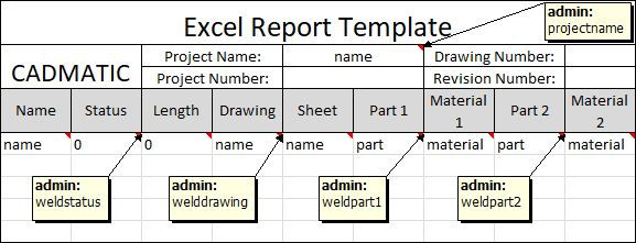
The following simplified example illustrates the usage of keywords in the template file for an Excel format export.
Excel template, comments (notes) shown:
The texts in row 5, except cell C5, can be changed to be any desired text string, for example all could be changed to a more generic string. The point is that each cell in this last row must have content that indicates which type of data the cell contains. Therefore cell C5 for the weld length contains a number (use the desired number of decimal places, 2 in this case).
This template will result in the following output: