Catalog Parts
Catalog parts are used to bind the component's geometry to certain dimensions and to provide information such as the materials and the standard to the following types of objects:
- piping components
- standard components
- joint materials
- beams
- plates
- cable tray parts
Typically, this data appears on bill-of-material lists extracted from the 3D model.
You can also send this data to the P&ID database, if using the integration.
All components that refer to the same catalog part share the same general information concerning the material, description, rating, and so on. However, size-dependent data remains separate for each component. The physical dimensions of a component (including weight) are stored in the Dimension Tables. Multiple parts can refer to the same dimension table—for example, when they have the same dimensions but are made of different materials.
Creating a new catalog part
You can create new catalog parts as needed.
Prerequisites
-
A dimension table for defining the part's dimensions.
-
Connection face definitions for connecting to other parts in the 3D model.
Do the following:
-
In the Project Environment dialog, browse to [library] > Components > Catalog Parts > Catalog Parts.
-
Do one of the following:
-
Select New > Catalog Part.
-
Make a copy of an existing part, then rename and open the new copy.
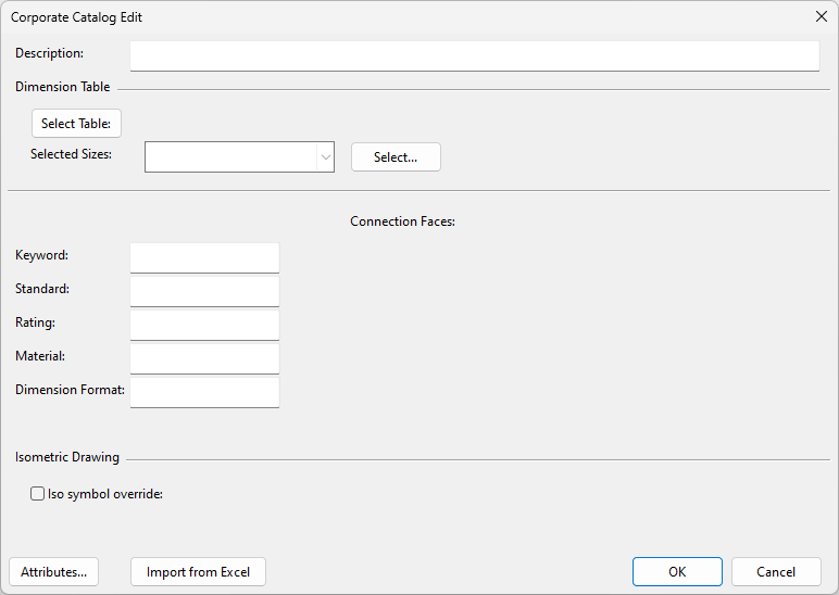
The Corporate Catalog Edit dialog opens.
-
-
If you have defined the values of the part in a Microsoft Excel file, import them as described in Creating catalog parts by import from Excel. Otherwise, define the values below manually.
-
Description – Enter a descriptive name for the catalog part.
-
Select Table – Select the dimension table that defines the dimensions of the catalog part. Leave the Selected Sizes field empty for now.
-
Connection Faces – Select a connection face type for each connection in the component.
-
Keyword – Right-click and choose the keyword from the list.
-
Standard – Right-click and choose the standard from the list.
-
Rating – Right-click and choose the rating from the list.
-
Material – Right-click and choose the material from the list.
-
Dimension Format – Right-click and choose the Dimension format to use, or type the format directly into the field. (This affects how the part sizes are displayed.)
-
Selected Sizes – Click Select to select the allowed part sizes. (This cannot be done before Dimension Format is defined.)
-
Iso symbol override – Select this option and click Select to choose a specific symbol for the part in isometric drawings.
-
Attributes – Click Attributes to assign attributes to the catalog part and define their values.
-
-
Click OK to save the new catalog part.