Editing a section
You can modify the boundary curve and hole curves of a section.
Editing a section
You can edit the boundary curve of a primitive.
Do the following:
-
Select Component Modeller tab > Edit group > Primitive.
-
Pick the primitive you want to edit and press Enter.
-
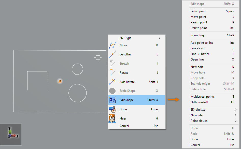
Right-click the view and select Edit Shape from the context menu.
The section editor is activated and you can right-click the view to access the tools described in Section editor context menu.
-
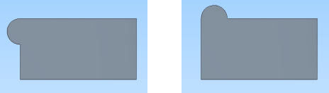
You can add rounding to corners or remove previously added rounding. You cannot edit the rounding of a primitive that has been inserted as a Rounded Rectangle.
 Show/hide details
-
Click near the corner to be rounded, so that the corner point is activated but not selected for moving.
-
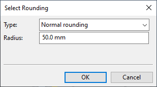
Press Alt+R to activate the Rounding command. The Select Rounding dialog opens.
-
Do one of the following:
-
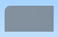
To add normal rounding, select Normal rounding and specify the radius.
-
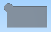
To add rounding with an offset, select Mickey Mouse rounding, specify the radius, and specify the offset from the corner point.
-
To add rounding on one side of the corner, select One-sided rounding and select the side.
-
To remove rounding, select No rounding.
-
-
Click OK. The rounding is applied to the specified corner. You can continue adding rounding to other corners in the same way.
-
-
You can manipulate line segments.
Show/hide details
-
You can select a line by clicking (or pressing Space) near the line segment. Then you can use the tools described in Line tools.
-
You can directly start moving a line by clicking the handle of the line.
-
You can edit a straight line segment:
-
You can insert new control points with Add point to line and then move those points as required.
-
You can turn a straight line into a curve with Line -> arc or Line -> bezier.
-
You can remove a line segment with Open line and then close the gap by adding one or more new line segments.
-
-
You can delete the selected line by pressing Delete.
-
-
You can manipulate control points.
Show/hide details
-
You can select one control point by clicking near the point. Then you can use the tools described in Point tools.
-
You can directly start moving a control point by clicking the point.
Tip: You can enable Ortho on/off to limit the movement to horizontal or vertical direction.
-
You can select multiple control points if you first enable the Multiselect points option and then click near the points that you want to select.
-
You can delete the selected points by pressing Delete.
-
-
You can add holes to the plate as described in Defining holes and manipulate existing holes with Hole tools.
-
Press Enter or select Done from the context menu to close the section editor.
Defining holes
You can add holes to a primitive.
Do the following:
-
Select Component Modeller tab > Edit group > Primitive.
-
Pick the primitive you want to edit and press Enter.
-
Right-click the view and select Edit Shape from the context menu.
-
Move the cursor to the intended location of the hole.
-
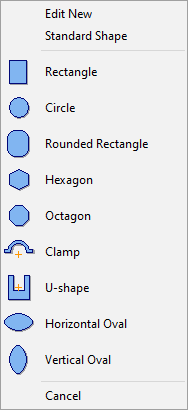
Press N to activate the New hole command. The Select Plate Shape dialog opens.
-
Select the method to use for defining the shape of the hole.
Show/hide details
-
Select Standard to create a hole whose shape is completely predefined and size parameters are defined during the insertion. After the insertion, the size parameters can be adjusted with Edit shape.
For more information, see Standard shapes.
-
Select Custom template to create a hole whose initial shape is predefined and size parameters are defined during the insertion. After the insertion, the shape can be freely changed by manipulating the control points and line segments.
For more information, see Template curves.
-
Select Define manually to create a hole whose shape is completely user-defined. The inserted hole has editable control points, so the shape can be changed also later.
For more information, see Edit new shape.
-
-
Define the parameters of the hole or change the shape or the size of the hole manually, as allowed by the type of the shape.
-
You can change the location of the selected hole with Move hole or Set hole Origin.
-
You can make copies of an existing hole with Copy hole.
-
Press Enter or select Done from the context menu to close the section editor.
Defining snap and grid settings
You can set the grid to be shown or hidden and choose whether the cursor moves freely or a specific distance at a time. Only rectangular grids are supported.
Do the following:
-
Right-click the section editor and select Navigate > Grid & Snap Settings. The Snap and Grid dialog opens.
-
Define the settings:
-
Show Grid [F7] – Select this option to show the grid.
-
Show as Lines – Select this option to show the grid as lines instead of dots.
-
Use Snap [F9] – Select this option to set the cursor to move according to the snap spacing settings.
-
Color – Select the color of the grid.
-
Grid spacing U, Grid spacing V – Specify the grid spacing in horizontal and vertical direction in millimeters.
-
Snap spacing – Specify the snap interval in horizontal and vertical direction.
-
Base U, Base V – Specify the base point to use for grid and snap, in horizontal and vertical direction.
-
-
Click OK.
