Cables
In the Cable Manager dialog, on the General tab, the Cables section contains tools for creating and managing 3D cables.
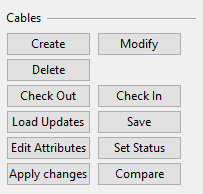
Create
You can create new 3D cables that are connected to equipment in the 3D model. If the head and tail objects do not exist yet, you can specify the cable end locations in model coordinates manually or by using a script.
Prerequisites
-
Optionally, the Cables settings specify a script that assigns end coordinates for cables whose head or tail object is not modeled yet.
Do the following:
-
Start cable creation from the Category tree in Cable Manager:
-
To create cables manually, select Cables > Not Routed. (After creation, the cables appear there.)
-
To copy existing cables, browse to the appropriate category and select the cables.
-
To create cables from data defined in another application, browse to Not created diagram cables and select the cables.
-
-
Select General tab > Cables section > Create.
-
If prompted whether to create cables from diagram cables, select Yes. This creates those cables, if possible, and places them in Cables > Not Routed.
 Show/hide details
Cables that have been defined in Electrical or P&ID can only be created if one of the following rules can be applied to each cable:
-
The head/tail objects are already found in the 3D model.
-
The program can get coordinates for cable ends from a script.
-
You pick the cable end locations from the 3D model, when prompted to do so.
Otherwise, the creation process fails.
-
-
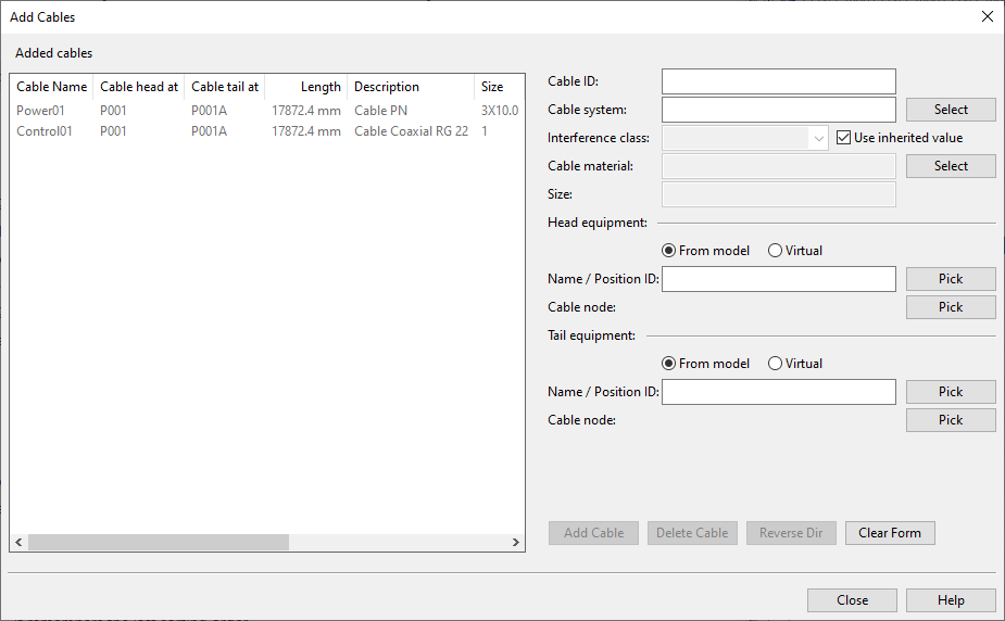
The Add Cables dialog opens. If copying existing cables, the dialog lists the cables you chose.
Define each new cable as follows:
-
Optionally, select an existing cable from the list to use it as a template.
-
Specify the properties of the new cable.
-
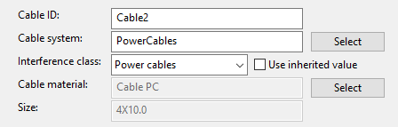
Cable name – Enter a unique name for the cable.
-
Cable system – Select a system for the cable.
-
Interference class – Select an interference class from the list, or choose Use inherited value to allow the cable to use the interference class defined for the system.
-
Cable material, Size – Click Select to choose the material and the size.
-
-
Define head and tail equipment; 'head' is where routing starts, 'tail' is where it ends.
-
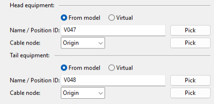
If the head and tail equipment are in the model, select From model and specify the following:
-
Name / Position ID – Enter the equipment's position ID or click Pick to select from the model.
-
Cable node – Select the required electrical node from the drop-down list.
If unsure, click Pick to view nodes in the model. Switch nodes by pressing Space or clicking, and press Enter to confirm.
Note: If no electrical nodes exist, other node types can be selected. If there are no nodes at all, choose 'Origin'.
-
-
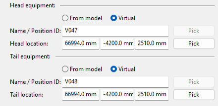
If the head and tail equipment are not in the model, select Virtual to connect the cable to a virtual definition:
- Name / Position ID – Enter a position ID not used in the model.
- Head location, Tail location – Enter XYZ coordinates or click Pick to select from the model.
-
-
Click Add Cable.
-
If prompted that the given position ID is reserved by an EDM object ('External Position ID Status' = 'Reserved'), select Yes to link the 3D cable to the externally defined cable, or No to use another ID. If the position ID is deleted by an EDM object, you must use another ID.
-
If head and tail are in the wrong order, select the cable and click Reverse Dir.
-
-
When finished, click Close to accept changes and return to the Cable Manager dialog.
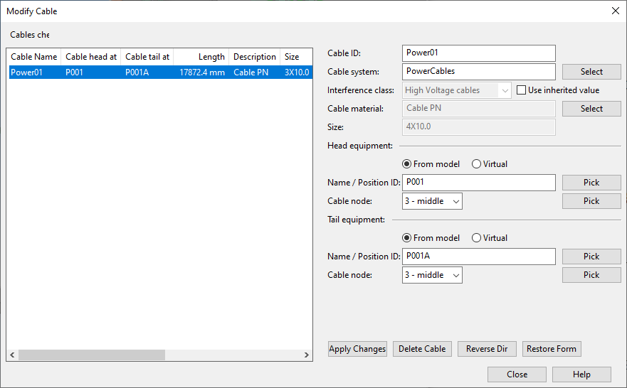
Modify
You can modify existing 3D cables.
Prerequisites
-
The cables are checked out to you and 'Cable status' is not 'Approved' or 'Deleted'.
Do the following:
-
In the cable list, select the cables you want to modify.
-
Select General tab > Cables section > Modify.
-
The Modify Cable dialog opens.
Make the required changes:
-
To edit cable properties, select and modify the cable, then click Apply Changes.
If prompted that a position ID is reserved by an EDM object ('External Position ID Status' = 'Reserved'), select Yes to link the 3D cable to the externally defined cable, or No to specify a different ID for the 3D cable.
-
To switch the head and tail, select the cables and click Reverse Dir. If you reversed only one cable, click Apply Changes.
Note: If reversed cables have Pull Markers, the program automatically recalculates the distances from head and tail to the pull marker.
-
To delete cables, select the cables and click Delete Cable.
-
-
Click Close to save the changes and return to the Cable Manager dialog.
Delete
You can select cables (checked out to you, not approved) and click Delete to delete them.
Deleting a 3D cable that was originally defined in P&ID returns the cable to the Not created diagram cables category.
Check Out / Check In
Select the cables you want to edit and click Check Out to check out the cables from COS.
Select the cables you no longer want to edit and click Check In to check them in to COS.
Note: If using Sister Project Management, checking out a cable in a target project will automatically unlink the cable. Checked out cables and cable network parts can be relinked to sister project as described in Link objects to sister project.
Load Updates
You can click Load Updates to load the data that other Plant Modeller areas have recently updated to COS.
Save
Click Save to save the currently defined cables to COS.
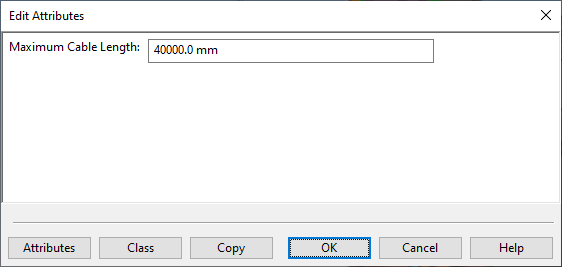
Edit Attributes
You can click Edit Attributes to open a dialog where you can select which attributes to include in the selected cables and define their values.
Cable Attributes from Plant Modeller
A 3D cable can have the following attributes:
-
Maximum Cable Length – Defines the maximum length of a cable run, measured from the head equipment to the tail equipment, excluding any extra lengths that may be defined in the configuration. If the cable material imposes a maximum run length, define this attribute in the related Catalog Part (or Part Size, if the restriction is size-specific) to ensure that all cables using that material inherit the maximum length from the library or project database.
For more information on cable length calculation, see Cable length calculations.
Cable Attributes from P&ID Integration
The 3D cable inherits the attributes of the P&ID cable.
- If project administrator has assigned the attributes (tags) to the COS object type 'Diagram Cable', the attributes are shown in the Edit Attributes dialog.
- If project administrator has assigned the attributes (tags) also to the COS object type 'Cable', the attribute values can be edited in the Edit Attributes dialog.
You can use the Compare tool to check whether the attribute values are the same in 3D and in the original diagram.
Removing an Attribute from a Cable
To remove an attribute from a cable, clear the attribute value.
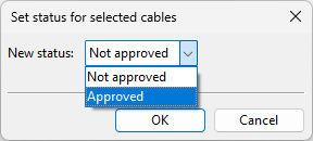
Set Status
Select one or more cables and click Set Status to open a dialog where you can set the status of the cables to either 'Not approved' or 'Approved'. Approved cables cannot be modified.
Tip: You can add 'Cable approved by' (.GI) to the columns of the cable list to see who has approved a specific cable and when.
Apply changes
You can use the Apply changes command when a cable's end location has changed in the 3D model and you want to apply the change to the cable in the cable router. This can be, for example, a change in the position ID or a change in the physical location.
The program tries to apply the change, and you are prompted in the following cases:
-
If only one cable end or both need to be changed and it cannot be done, a failure is reported.
-
If both cable ends need to be changed and only one succeeds, then one end is reported with the status 'ok' and the other with 'error'.
-
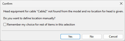
If equipment is no longer present, the program suggests using virtual equipment for that cable end.
-
If equipment is now available for a diagram cable that has been using virtual end locations specified by the user or a script.
Tip: You can do this also with the context-menu command Apply changed end locations.
Compare
You can compare 3D cables to the respective cables defined in an external program or in CADMATIC Electrical or P&ID to see if there are any differences in the data.
For more information, see Compare to integrations.