Diagnostics
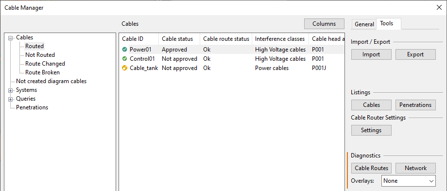
In the Cable Manager dialog, on the Tools tab, you can run diagnostic analyzes that provide information about a single cable's route or about the cable routing network.
You can run diagnostics on a cable to find out the following:
-
The route that is proposed as the best for that cable.
-
The kinds of problems that other routes may have.
-
Whether any cable goes directly from one piece of equipment to another, without passing through cable ways.
You can run diagnostics on the cable routing network to identify any orphaned items or overfilled segments.
Cable Routes
In the Diagnostics section, the Cable Routes tool might be able to find a route even if automatic routing did not find one, or it might find a route that is shorter than some of the other routes but has some (possibly removable) problem that caused automatic routing to reject it.
Use the information provided by the tool to decide whether to select a new route or keep the existing one.
Prerequisites
-
Check out the cable, if you intend to change the route. See Check Out / Check In.
Do the following:
-
In the Cables pane, select the cable to be diagnosed.
-
On the Tools tab, in the Diagnostics section, use the Overlay drop-down menu to select what differences between the nodal network and the 3D model you want the visualization of the routes to show. For details, see Overlays.
-
On the Tools tab, in the Diagnostics section, click Cable Routes.
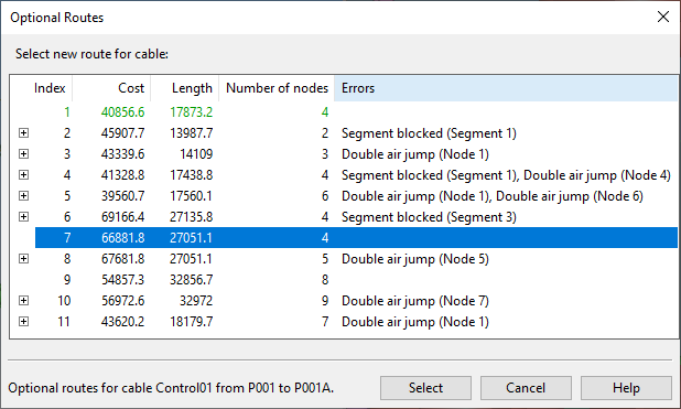
The diagnostics process runs and then the Optional Routes dialog opens, listing the possible routes for this cable. If the automatic routing found a preferred route, it is displayed in green text. The rest of the list is ordered based on the "cost" of each route. For more information on how cost is calculated, see Cable route cost calculations.
Note: If the head or tail equipment does not have an electrical node, the cable cannot be routed and the program shows an error message instead of the Optional Routes dialog.
-
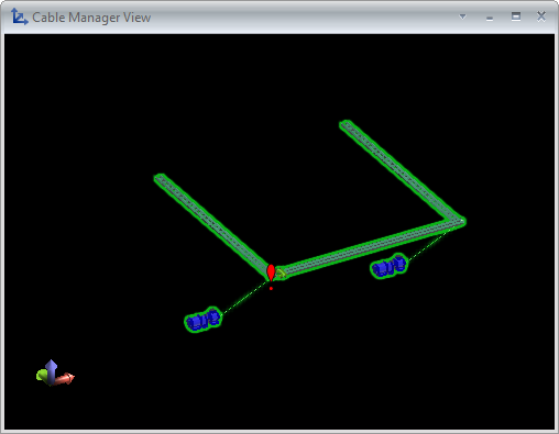
You can select a route from the list to show its visualization in a separate view. The visualization shows all the nodes, segments, and related parts such as cable trays and penetrations, and also the head and tail equipment.
-
If the diagnostics reported errors, expand the error list.
 These errors are reported:
-
Double air jump
Cables are not allowed to be routed via double air jumps. Cables can jump directly from equipment to another equipment, but when jumping from equipment to cable tray/pipe/penetration there must be at least one segment in between.
-
Fill rate blocked
Cable cannot use the segment anymore because, for example, the cable tray is already full or the segment is too small for a single large cable.
-
Fill rate error, cable tray width exceeded
Segment might still have plenty of space, but the width of the segment is exceeded.
-
Fill rate error, cable width or height missing
Cable tray where the segment is does not define width or height for the cable.
-
Fill rate error, cable with invalid reference class detected
Segment contains routed cables whose interference class is invalid.
-
Fill rate error, no suitable sealing modules
Segment is an MCT penetration segment, but there are no sealing modules defined for it.
-
Head and node are not located in same compartment
Tail and node are not located in same compartment
The equipment and the targeted node are not located in the same compartment, and the distance between them does not exceed the maximum head/tail jump value defined in cable router settings by more than 1 m. If they are further away from each other, then the route is not listed at all.
-
Head and tail not located in same compartment
Direct jump is not possible because the head and tail equipment are not located in the same compartment.
-
Head and tail too far from each other
Direct jump is not possible because the distance between the head and tail equipment is more than the maximum direct jump value defined in cable router settings. If the maximum distance is exceeded by more than 1 m, then the route is not listed at all.
-
Jump too long between node and head
Jump too long between node and tail
The distance between the equipment and the targeted node is more than the maximum head/tail jump value defined in cable router settings, and the distance between them does not exceed the maximum head/tail jump value defined in cable router settings by more than 1 m. If they are further away from each other, then the route is not listed at all.
-
No nodes found with node id from head/tail equipment
Cable can only jump from the head/tail equipment to a node that has a node ID. This means that the first and the last route node that the cable uses must have a node ID. Node IDs can be added manually or generated, as described in Nodal Network.
-
Route length exceeds the maximum length set for the cable
Cable has a maximum length defined in an attribute and the route exceeds that length.
-
Segment blocked
Another 3D object is placed so that it blocks the segment. If these errors are false alarms caused by object types that the diagnostics check should ignore, define the objects in the model query of the Objects ignored at air jumps setting, as described in Network.
-
Segment / Node disabled
Cable can only be routed via enabled segments and nodes. The user can disable segments and nodes, as described in Modify.
-
Space for direct route is not clear
Direct jump is not possible because there is an object blocking the direct route from one equipment to the other. Only reported if the head and tail equipment are not inside a compartment.
-
Space from equipment to node is not clear at head
Space from equipment to node is not clear at tail
There is an object blocking the route from the node to the equipment. Only reported if the equipment is not inside a compartment.
-
Wrong interference class
The cable uses a System or a separately specified interference class that is not allowed in the System of the host object (such as cable tray).
You can select a row from the error list to show the problem in the visualization view. In the visualization view, the errors are indicated with red exclamation marks.
You can click the visualization view and zoom in to the problematic area to examine the issues visually.
Press Esc when you want to return to the Optional Routes dialog.
-
-
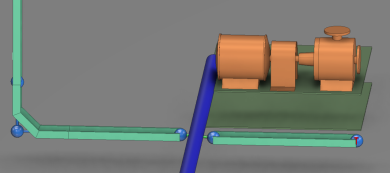
If you selected an overlay option, the visualization shows the specified overlay icons. For example, if you selected the Show open ends option, the view shows a marker next to all cable nodes that have only one valid segment.
 Show/hide example
The following example shows a pipe blocking the segment creation, and the nodes that it blocks are displaying the “Show open ends” icon.
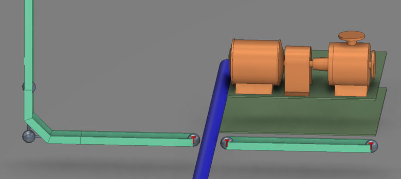
When this occurs, you can use the Modify tool in the Nodal Network section of the Tools tab to create a user-defined segment between these problematic nodes and thus correct the issue. If the problem is removed, the visualization is automatically updated and the icons disappear. See Modify.
-
If the cable is checked out, do one of the following:
-
Select a new, error-free route for the cable and then click Select.
-
Click Cancel to keep the existing route.
-
-
If the cable is checked in, click Close.
Network
In the Diagnostics section, the Network tool checks selected cable routes for these problems:
-
Orphan cable network nodes.
-
Orphan cable network segments.
-
Overfilled segments.
Note: Opening the Cable Router dialog runs this tool automatically, but the results are only shown if errors were found.
Do the following:
-
In the Cables pane, select the cables to be diagnosed.
-
On the Tools tab, in the Diagnostics section, click Cable Routes. The diagnostics process runs and then a dialog opens, indicating if any errors were found.
-
Click OK.
-
If problems were found, on the Tools tab you can enable overlays to see where the problems are in the model. For details, see Overlays.
