Using the smart cursor and assistance points for navigation and routing
CADMATIC has a smart 2D/3D cursor and assistance point function that together help the user navigate within the work views and to select the required entities.
General cursor properties
The cursor displays the main coordinate axes of the model, which are also shown in the lower-left corner of the work view, as well as information related to the current context.
The cursor can display the following information to the user:
-
Axis line color indicates axis type: X-axis is red, Y-axis is green, and Z-axis is purple.
-
Axis line length indicates the direction along the axis: the line is longer in positive direction than in negative direction.
-
Normally the axis line is solid, but it becomes striped when it is behind or inside a model object.
-
Tooltips next to the cursor display HUD messages and prompts, when enabled. See HUD for details.
-
When selecting objects:
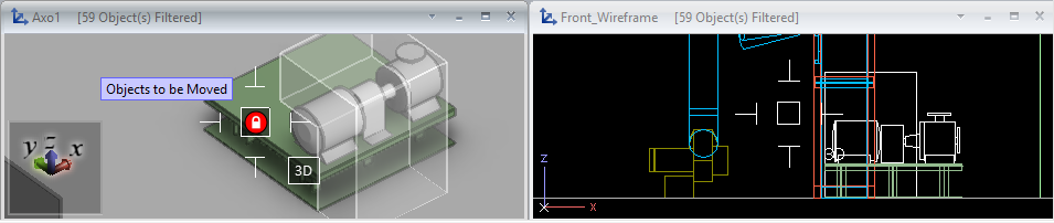
- If 3D hit is on, the cursor displays the text '3D', and moving the cursor inside an object highlights the object.
- The size of the cursor reflects the object hit distance: increasing the hit distance value increases the size of the cursor.
- A lock icon on red background indicates that the selection is not possible in the current context. This happens, for example, when the object is not checked out or it is not within the hit distance.
-
When routing, a rubber band line shows the cursor's position relative to the last selected routing point.
-
When the cursor is constrained to object centerline or edge (for example, when routing a pipe or snapping to centerline), one or more text labels are displayed to show distance information. These text labels are input fields that you can activate with Ctrl+Tab to modify the value. Press Enter to accept the new value or press Esc to cancel editing.
Cursor and assistance points
In the Plant Modeller user interface options described in Assistance geometry, you can select whether to display and highlight assistance points in shaded views. When any assistance point types are enabled and the cursor stops moving, the active view displays points located within the maximum search distance defined in the options. Some point types are only visible in Component Modeller.

The color and shape of an assistance point indicate its type.
-
Connection points:
-
 Yellow circle – Connection point with no flow direction.
 -
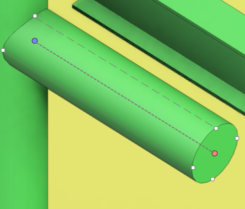
 Purple circle – Connection point with inward flow direction.
 -
 Red circle – Connection point with outward flow direction.
 -
Geometry points:
-
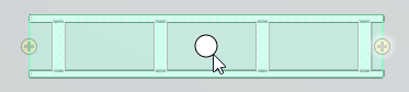
 White circle – Center point of the centerline of an air duct, beam, cable tray, or straight pipe. Center point of an arc or circle. Auxiliary point with no flow direction.
 -
 Cyan circle – Beam point.
 -
 Light yellow circle – Weld point.
 -
 Green triangle – Pipe branch point.
 -
 Orange circle – Named point.
 -
 Yellow/black circle – Center of Gravity (CoG) for Mass.
 -
 Green/black circle – Center of Gravity for Operational Mass.
 -
 Pink/black circle – Center of Gravity for Maximum Mass.
The program highlights the assistance points closest to the cursor to indicate the target point if the user performs an action that targets a specific point type. For example, Move to nearest geometry point (W) goes to the highlighted geometry point, and Move to nearest connection (Q) goes to the highlighted connection point. The maximum distance for such actions can be defined in the Tolerances user options.
When an assistance point is directly under the cursor, the program enlarges it, and if HUD is enabled, shows additional information about the point in the tooltip. If the point is a connection point, a flow direction arrow in the same color is also shown.

Assistance points are shown as dimmed when they are inside an object or when they are behind an object and at least part of their parent object is visible. Dimmed points can also be navigated to.
In the example below, the left picture shows a cable tray connection point and two cable penetration connection points behind a wall, as their parent objects are partially visible, while the right picture shows a filter box set to the wall boundary, so the cable tray and its connection point are no longer visible.

Cursor and object centerline
The cursor visualizes the centerline of air ducts, beams, cable trays, and straight piping parts.
You can use Go to Nearest Centerline (F11 or Shift+C) to snap to the centerline.

Cursor and centerline center point
The cursor visualizes the center point of the centerline of straight air ducts, beams, cable trays, and piping parts, if centerline center points are enabled in the Assistance geometry settings.
You can use Move to nearest geometry point (W) to snap to the nearest center point, even if they are not visualized.
Cursor and quadrant points
The cursor visualizes the quadrant points and quadrant lines of straight piping parts.
-
Quadrant points are visualized if pipe geometry points are enabled in the Assistance geometry settings. You can use Move to nearest geometry point (W) to snap to the nearest quadrant point, even if they are not visualized.
-
Quadrant lines are visualized when pipe centerlines are visualized. You can use Nearest edge (Shift+E) to snap to the nearest quadrant line, in some contexts also when the lines are not visualized.
Cursor in set operations
When you are selecting objects or performing set operations such as move, copy, rotate, or delete, the cursor is displayed as a cross-hair.
The size of the box in the center indicates object hit distance, and a text label indicates if 3D hit is enabled.

Cursor axes and routing
When you start a routing command, the cursor axes extend across the whole work view, and striped sections indicate locations where the axes go through or behind objects. This allows seeing where exactly the cursor is located within the model area, and whether there are any objects in the intended routing direction, for example.
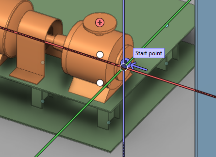
Cursor and starting point for routing
When you have selected a starting point for routing of, for example, structurals and cable trays, a white cross marks that point and a rubber band line follows the cursor to indicate current routing direction.

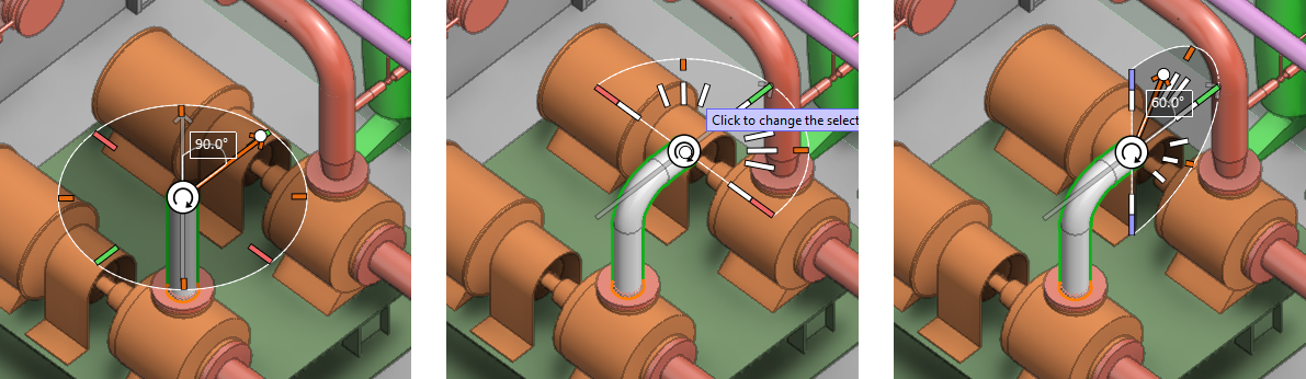
Cursor in selecting pipe routing direction
In pipe routing, when you have selected the starting point or an intermediate routing point and Use routing direction assist is enabled in the context menu, a graphical tool is displayed for selecting the next routing direction. For more details, see Use routing direction assist.
Cursor constrained to line
When the cursor is constrained to a line, only the coordinate axis line of that direction is visible to indicate that the cursor can only move in this direction. The line has the color of the relevant axis, or it is gray if the direction is not parallel to any main axis.
Moreover, when the cursor is constrained to line, one or more distance fields are displayed to indicate cursor's distance from specific points, such as distance from the current starting point of routing. You can also edit these distance values to move the cursor to the designated location: press Ctrl+Tab to activate the field, and enter the distance value to navigate to.
Constrained cursor can be released by pressing Shift+A.

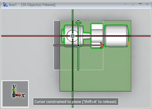
Cursor constrained to plane
When the cursor is constrained to a plane, a dashed square is drawn around the cursor's location.
Constrained cursor can be released by pressing Shift+A.
Cursor with spherical coordinates
After using the Set radius and angle (S) command, but also in some other contexts, the smart cursor visualizes the phi (f) and beta (b) angles, and the spherical coordinates are also shown as text at the bottom of the screen.
- b = beta, the elevation angle from the x-axis (slope angle)
- f = phi (fii), the azimuth angle from the x-axis (rotation angle in horizontal plane)
- r = radial distance from the fixed point of origin

