Visualization control
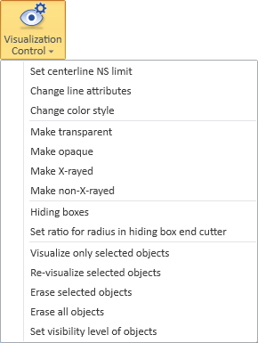
On the Home tab, in the Show group, the Visualization control menu includes the following tools for controlling the content of work views. Visualization attributes are assigned to objects using different types of masks. A common method is to group objects with similar visualization attributes.
Use visualization control before generating work views for documents. All new components inserted into the model will be visualized with default attributes.
Some commands require the view to be redrawn or regenerated to apply the new visualization attributes.
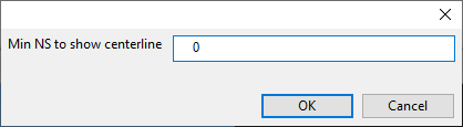
Set centerline NS limit
You can specify a minimum Nominal Size value for visualizing the pipe centerlines. If a pipe is smaller than this value specifies, then the centerline is not visualized.
Do the following:
-
On the Home tab, select Visualization Control > Set centerline NS limit.
-
Select the views where you want the setting to be applied and click OK.
-
Enter the required value and click OK.
-
Regenerate the views or re-visualize the objects to apply the new setting.
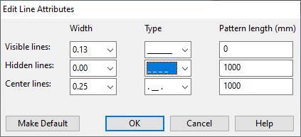
Change line attributes
You can change the line attributes of a set of objects in an open wireframe view.
Do the following:
-
On the Home tab, select Visualization Control > Change line attributes.
-
Select the required objects and press Enter.
-
Select the wireframe views where you want the change to be applied and click OK. The Edit Line Attributes dialog opens.
-
Edit the line attribute values as required and click OK.
- Re-visualize the objects.
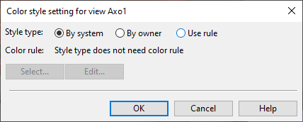
Change color style
You can set model objects in work views to be colored based on their system, their current owner, or surface shading rules. The default color style is defined in the user settings, as described in Colors.
Do the following:
-
On the Home tab, select Visualization Control > Change color style. The Select Views dialog opens.
-
Select the required views from the list and click OK. The Color style setting for view… dialog opens.
-
Select what defines the color of the model objects:
-
By system – Select this to color the objects based on the System they use. For information on defining system colors, see Creating systems.
-
By owner – Select this to color the objects based on who owns them. For more information, see Color objects by ownership.
-
Use rule – Select this to color the objects based on a Surface shading style.
-
Select – Opens a list of available surface shading styles for selecting which style to use.
-
Edit – Opens the current style for editing.
-
-
-
Click OK.
Make transparent
You can make objects transparent. This is useful especially when there are large tanks or walls and you want to see the objects behind them.
![]()
Do the following:
-
On the Home tab, select Visualization Control > Make transparent.
-
Select the objects you want to make transparent and press Enter.
-
Select the views where you want the change to be applied.
-
Regenerate the views.
Make opaque
You can make transparent objects to be solid again.
Do the following:
-
On the Home tab, select Visualization Control > Make opaque.
-
Select the objects you want to make opaque and press Enter.
-
Select the views where you want the change to be applied and click OK.
-
Regenerate the views.
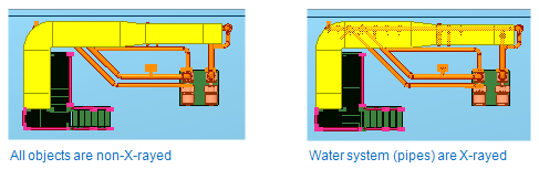
Make X-rayed, Make non-X-rayed
You can specify whether specific objects can be seen through other (opaque) objects.
Do the following:
-
On the Home tab, select Visualization Control > Make X-rayed or Make non-X-rayed, as applicable.
-
Select the objects you want to be X-rayed / non-X-rayed and press Enter.
-
Select the views where you want the change to be applied and click OK.
-
Regenerate the views.
Hiding boxes
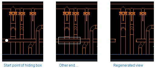
A hiding box hides a segment of a straight pipe or a straight duct whose centerline passes through the box, to show the objects that are behind the hidden segment. Hiding boxes are often used in drawing views to make drawings more readable and to reduce the number of separate drawing views, but they can also be used in wireframe work views. One hiding box can cut several pipes, or one pipe (or duct) may be cut by several hiding boxes. The hiding boxes themselves are only visible while you are editing them.
How to use hiding boxes
-
On the Home tab, select Visualization Control > Hiding boxes.
-
Select the wireframe view from the list.
If there are existing hiding boxes in the view, you can now see them in all the open views.
A small cursor is shown and this you use either to pick or edit an existing box or to indicate the start point of a new box. To select a box move the cursor inside the box. When the editor notices this it marks the end points of the box. Also the end point that would be the target for move or stretch command is marked with a small rectangle. These marks at the end points indicate which hiding box is currently selected. Editing actions will be applied to this box.
Edits made to the hiding boxes are applied to 3D objects when you regenerate the view, visualize or re-visualize a set into the view. Use one of these commands when you have completed editing hiding boxes.
Create a new hiding box
-
Move the cursor to a place where you want the new hiding box to start.
-
Select Create new or press N.
-
Define the other end of the hiding box. While you move the endpoint the system animates the hiding box with default cross-section dimensions in all views. Accept the point or press O to accept the point and define the cross-section of the box.
-
Select Done. You can see the new hiding boxes after you have regenerated the view, visualized or re-visualized a set into the view.
Setting cross-section dimensions
-
Select the hiding box.
-
Select Cross-section or press O.
-
Pick cursor disappears and editor starts to track a point that is in one of the corners of the box. Cross-section dimensions change as you move the point. The length or the orientation of the box is not changed. Press I if you want to enter exact dimensions for the width and height of the box.
Move the hiding box
-
Select the hiding box.
-
Select Move or press K.
-
Pick cursor disappears and editor starts to track a point that is at the active end point. As the result the box moves.
-
Use the point definitions rules when you accept a new location.
Stretch the hiding box
You can stretch the existing hiding boxes.
-
Select the hiding box.
-
Select Stretch or press I. Pick cursor disappears and editor starts to track a point that is at the active end point. The other end point stays in place. As result the box is stretched and rotated.
-
Use the point definitions rules when you accept a new location.
Remove the hiding box
You can delete the existing hiding boxes.
-
Select the hiding box.
-
Select Remove or press U. The selected box is removed.
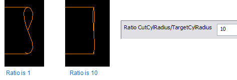
Set ratio for radius in hiding box end cutter
Radius of the cutting cylinder is proportional to the radius of the cylinder that is been hidden. The purpose of this command is to make the end cuts smoother. The application default database entry: "ViewMgm/HboxCutRR" can be set to specify the ratio cut_r/cyl_r. Values less than 1.01 are forced to be 1.01. If the app default is not defined then a default value 1.5 is used. Maximum value is 100.
The app default is retrieved only once during a Plant Modeller session. If you change this app default in a Plant Modeller session then it will become effective only after you restart Plant Modeller and regenerate the view.
Visualize only selected objects
You can specify that only certain model objects appear in specific work views.
Do the following:
-
On the Home tab, select Visualization Control > Visualize only selected objects.
-
Select the objects you want to visualize and press Enter. The Select Views dialog opens.
-
Select the views where you want to apply the change and click OK. Only the selected objects are visible in the specified views.
Re-visualize selected objects
You can re-visualize objects in specific work views.
If the view has been used in a drawing, the line attributes and transparency of objects already included in the view remain unchanged. Otherwise, these values are reset to their default settings.

If the view has been used in a drawing, the line attributes and transparency of objects already included in the view remain unchanged. Otherwise, these values are reset to their default settings.
This command is useful, for example, when Hiding boxes are modified, and the changes affect only certain objects.
Do the following:
-
On the Home tab, select Visualization Control > Re-visualize selected objects.
-
Select the objects you want to be re-visualized and press Enter. The Select Views dialog opens.
-
Select the views where you want to apply the change and click OK.
Erase selected objects
You can remove a set of objects from specific views.
Do the following:
-
On the Home tab, select Visualization Control > Erase selected objects.
-
Select the objects you want to be erased from views and press Enter. The Select Views dialog opens.
-
Select the views where you want to apply the change and click OK.
Tip: You can use the Model Tree pane to erase specific objects from all open views. See Managing tree items.
Erase all objects
You can remove all objects from specific views.
Do the following:
-
On the Home tab, select Visualization Control > Erase all objects. The Select Views dialog opens.
-
Select the views where you want to apply the change and click OK.
Set visibility level of objects
You can define the visibility level of objects. For details, see Filtering views by object visibility level.