Setting up WBD 3D sketches
Before Work BreakDown 3D sketches can be generated, some setup is needed.
Sketch layout
What information should be presented in the sketch and how it should be positioned is defined in the assembly sketch layout in System Management > Production > Assembly Sketch > Sketch Layout.
Sketch settings
The appearance of the items in the sketch can be defined with the various settings under System Management > Production > Assembly Sketch > Settings.
Here you can define the table properties, label properties, drawing properties, and also settings for the center of gravity (COG) markings and reference points, and some saving settings.
Center of gravity markings
The center of gravity (COG) point at the Work BreakDown level (subpanel, for example) can be shown in WBD 3D sketches.
The COG point is shown if the text for indicating it is defined. This can be done in System Management > Production > Assembly Sketch > Settings > COG Text, Text At COG Point setting.
Weld lines
The Create Weld Lines Models setting in System Management > Construction > Welds/Bevels > Settings must be enabled to show weld lines.
Also, a user-defined macro, calcweldinfo.cmd, must be present in the weld folder of the project norms in (<project>\norms\cvar\weld). No weld data is available without the macro. See calclweldinfo.cmd for more information and an example.
Tables
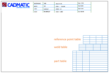
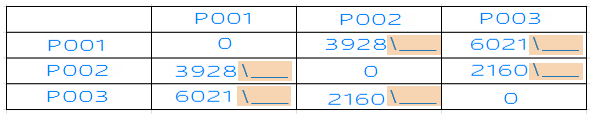
The following tables can be included in WBD 3D sketches: part table (also known as branch table), weld table and reference points table.
Pen selections and other appearance-related settings for the tables in the sketches can be set in System Management > Production > Assembly Sketch > Settings > Table Properties.
Report layout for the part table
To include a table presenting the parts in the sketches, a report layout must be defined for each WBD level. See Report layout for details on creating the report layouts for WBD 3D sketches.
Eextra space for manual user input in the reference points table
It is possible to have extra space added to the cells for manual user input by enabling the Reference Point Table Extra Space setting in System Management > Production > Assembly Sketch > Settings > Table Properties.
Positioning of the tables
How the tables are positioned in WBD 3D sketches is defined in the assembly sketch layout settings in System Management Production > Assembly Sketch > Sketch Layout, in the Sketch Layout dialog.
There are 8 fields available for positioning the tables. Each field defines a corner point for a box area where the table is placed. A box area can be defined for each of the table types. Also a common box area containing all the tables can be defined.
-
Table Branch, bottom left – The bottom left corner of the part (branch) table area
-
Table Branch, top right – The top roght corner of the part (branch) table area
-
Table reference points, bottom left – The bottom left corner of the reference point table area
-
Table reference points, top right – The top roght corner of the reference point table area
-
Table weld, bottom left – The bottom left corner of the weld table area
-
Table weld, top right – The top right corner of the weld table area
-
Tables, bottom left – The bottom left corner of the area containing all the tables
-
Tables, top right – The top right corner of the area containing all the tables
Note: When Tables, bottom left and Tables, top right are placed in the sketch layout, the corner points of the individual table types are not used, even if they are present in the sketch layout. The tables are positioned at the bottom right corner of the sketch so that the part table is located at the bottom, the weld table at the top of the part table, and the reference point table at the top of the weld table.
Keyboard shortcuts
Keayboard shortcuts s and z can be used for repositioning the corner points.
-
s starts the move function. See Move.
-
z starts the interactice move function. See Interactive Move.
Justification
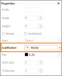
The Justification property can be used for the bottom left corner points of each table type (but not for Tables, bottom left).
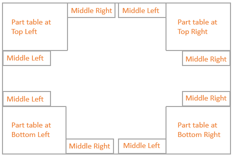
The tables using the Middle Left or Middle Right justification will be arranged so that they are connected and aligned with each other according to the selected justification options. This property is set in the Property dialog of the Sketch Layout settings.

Consider the following when setting the justification:
-
The part (branch) table can only be justified (placed) at the top left, top right, bottom left or bottom right position. If any other justification option is used for the part table, it will be placed at the bottom right.
-
All justification options can be used for the weld table and the reference point table.
-
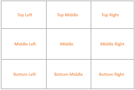
The middle justification option selected for the table determines on which side of the previously placed table it is placed. The image below maps out the positions of the weld table and the reference point table when Middle Left and Middle Right justifications are used.
-
When Middle Left and/or Middle Right justifications are used, the system places the tables in the following order: part table, weld table, reference point table. This means that:
-
The weld table will always be connected to the part table regardless of the position of the table area defined by the corner points.
-
The reference point table will always be connected to the weld table regardless of the position of the table area defined by the corner points.
-
If the weld table is not present, the reference point table will be connected to the part table.
-
Important: If the middle left or middle right justification is used for the reference point table, it will not be connected to the weld table unless the justification of the Table weld, bottom left field is set to a corner position.
Examples
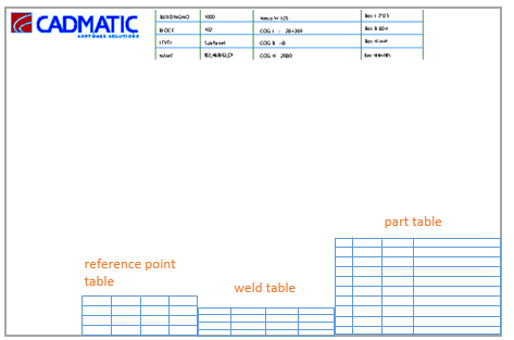
The part table is justfied to bottom right, the weld table to middle left and the reference point table to middle left.
In this case the weld table is connected to the part table on the left side and the reference point table is connected to the weld table on the left side.
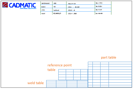
If the justification of the reference point table is changed to be middle right, the reference point table is moved to the top of the weld table, aligned along its right edge. This is because the reference point table will always be connected to the weld table when these justifications are used.
If the justification of the weld table is also changed to be middle right, the weld table and the reference point table will both be located at the top of the part table, on the right side of the sketch.