Creating shell plates by relations
Shell plates are created with the Shell application by adding shell plates in a shell view.
First you define the shell plate properties, and then the shell plate relations using either hull lines or fixed value borders or both.
See Modifying shell plates and Recalculating shell plates for information on how to modify and recalculate shell plates.
See Copying and moving shell plates over center line for information on how to copy and move shell plates.
Defining shell plate properties
Do the following:
-
Open a shell view: Select Home > Open in the Shell application, and select the shell view.
-
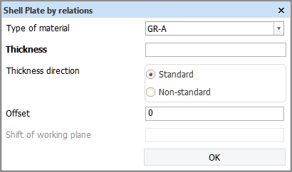
Select Construction > Insert > Shell Plate > Shell Plate by relations. The Shell Plates by relations dialog opens.
-
Select shell plate material type in Type of material.
-
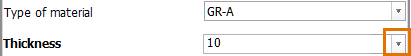
Enter or select the Thickness.
The Hull Administrator can set up restrictions for the plate and shell plate thickness for each material type by defining the permitted thicknesses in System Management > Construction > Plates > Thickness > Restrictions.
When thickness restrictions have been set for the selected material type, the thickness value is not entered into an input box. Instead, it is selected from a drop-down list consisting of pre-defined thicknesses.
-
Select the Thickness direction. The thickness direction aligns to the surface shape normal.
-
Standard – Thickness direction is the same as surface shape normal.
-
Non-standard – Thickness direction is the opposite of surface shape normal.
-
-
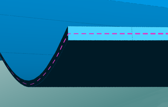
If needed, shift the reference plane of the shell plate: Enter the Shift of working plane. The value must be between 0 and the Thickness value. The default value is half of the thickness, meaning that when the shell plate thickness is 12 mm, the shift of working plane is 6 mm.
Setting the right shift of working plane is important for the correct expansion of the shell plate and to avoid conflict with the shell.
-
Set the Offset if needed. This is the distance between the molded line of the shell plate and the surface shape, by default 0, and can be a positive or a negative value.
-
Define the Shift of working plane if needed. This shifts the reference plane of the shell plate. This must be a value between 0 and the Thickness value. The default value is half of the thickness, meaning that when the shell plate thickness is 12 mm, the shift of working plane is 6 mm. Setting the right shift of working plane is important for the correct expansion of the shell plate and to avoid conflict with the shell.
-
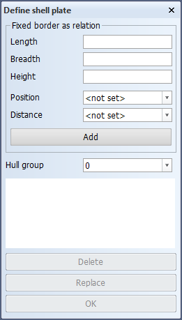
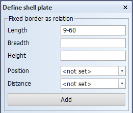
Once you have defined the shell plate properties, click OK. The Define shell plate dialog opens.
Next you define the shell plate relations as described in Shell plate relations below.


Shell plate relations
Once you have defined the shell plate properties as described in Defining shell plate properties, you define the contour of the shell plate by defining the relations of the shell plate. Shell plates can be related to hull lines and fixed value borders.
-
The relations must be indicated in counter-clockwise order.
-
The relation lines/borders must form a closed contour.
Hull lines as plate relations
To ensure that all the selected lines belong to the same hull group, the system only allows lines that belong to the same hull group as the first indicated line. But If no relation line has been selected yet, the selection of lines can be limited to a specific group also with the Hull group selection in the Define Shell Plate dialog.
The following hull line types can be selected as relation when inserting or modifying a shell plate:
- seams
- butts
- dimension lines
- all lines from the shape database, including hull boundary lines and groups intersection lines
Closed hull lines can be used as relations. This makes it possible to create cylindrical (even full 360 degree cylinders) shell plates. See Using closed hull lines as relations for more information.
Selecting hull lines as relations from Hull Viewer
Relation lines can also be selected from Hull Viewer both while creating a shell plate by relations and while modifying relations of an existing shell plate.
During shell plate relation selection, selecting a hull line in Hull Viewer will send it to Hull. Hull will then add this relation just as if it had been selected in the active shell view.
During shell plate relation selection Hull Viewer will be in a special state. This selection state has the following properties:
-
Left clicking a hull line will add it to Hull as a relation.
-
Regular selection is disabled.
-
Shell plates are shown as transparent.
-
Hull lines can be selected through or behind the transparent shell plates.
-
Other parts than shell plates are hidden from view.
-
All hull lines are shown thicker.
-
Added hull line relations are drawn with the Relation color, which is configurable from Preferences > Colors.
Hull Viewer enters the relation selection state when shell plate relation selection starts while Hull Viewer is open, or when Hull Viewer starts while shell plate relation selection is active. Hull Viewer cannot enter the relation selection state if one of the following is ongoing:
-
Weld Manager is open.
-
Work Breakdown Structure is open.
-
The user is choosing a file to open.
-
A .3hm file is open in Hull Viewer.
Note: Shell plates can be created and existing relation lines can be selected and modified from Hull Viewer also when there is no active shell drawing open. For modifications, Hull Viewer enters the relation selection state when the Modify Shell Plate Relations function is started in Hull.
Using hull boundary lines as relations
Hull boundary lines are read-only dimension lines on the outer edges of hull groups and at the boundaries of hull groups. These hull lines cannot be created, modified or deleted in the Shell application, but they can be used as relations when creating shell plates.
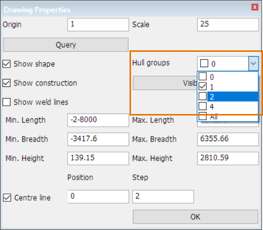
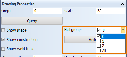
Note that adjacent hull groups both have a boundary line at the intersecting hull group boundary. If you want to create a shell plate that uses such a boundary line as a relation, make sure that the relation is to that boundary line which belongs to the hull group where you want to create the shell plate. Because the curves of the boundary lines between adjacent hull groups are identical, it may be difficult to select the right one. In that case you can make only the desired hull group visible in Drawing Properties, and thus hide the adjacent hull group.
See Hull boundary lines for more information.
Using groups intersection lines as relations
Groups intersection lines are read-only hull lines at the intersections of the shapes of adjacent hull groups. These hull lines cannot be created, modified or deleted in the Shell application, but they can be used as relations when creating shell plates. Because intersecting hull groups have identical groups intersection lines at their intersection point, by relating a shell plate to a groups intersection line you can make the shell plate contour follow the shape of the intersecting hull group. You relate the shell plate to the groups intersection line located in the same hull group as the shell plate, not the line in the intersecting group.
To show the groups intersection lines in the other (intersecting) hull group, select the group from Hull groups in Drawing Properties.
See Hull group intersection lines for more information.
Hull groups with both hull boundary lines and groups intersection lines
It may be difficult to distinguish between hull boundary lines and groups intersection lines in the view when the lines are at the same location, and thus relate a shell plate correctly to the desired hull line type. In these cases, either deselect the other hull line type in Show Hull Lines, or remove it from the view with the Hide Hull Lines function.
Using closed hull lines as relations
Closed hull lines can be used as relations for shell plates. This makes it possible to create cylindrical shell plates.
Important: The Shell Plate by Relations function should always be used when creating shell plates with closed hull lines as relations, not the Enclosed Shell Plate function. Also, do not use fixed value relations.
When a set of four relations defines two closed contours, it is possible to create two different shell plates using the same the relations. In these cases the location of the indication point when selecting a relation makes a difference. The system selects that part of the hull line which is nearest to the indication point as a relation. Also, the shell plate will be created in that closed contour where the indication point is located.
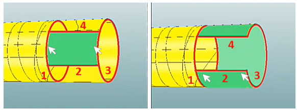
The green area shows shell plate that is created. The arrows show indication points for relations 1 and 3.
Closed shell plates: Closed (360 degree), fully cylinder-shaped shell plates cannot be created by using just one or two closed hull lines as relations. Doing so can lead to unpredictable results, and the resulting shell plate cannot be unfolded or coded. A closed shell plate must be related to three hull lines: two closed hull lines and a seam, butt or dimension line. In these cases the hull line which is not one of the closed hull lines must be selected twice as a relation.
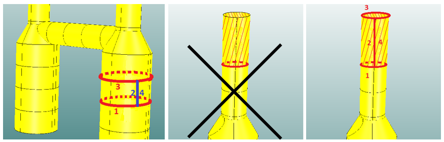
Left: Vertical dimension line selected twice as a relation (2, 4) – Middle: Incorrect relations – Right: Correct relations
Note: It is not possible to unfold and code a closed, 360 degree fully cylinder-shaped shell plate. The shell plate needs to be cut somewhere. Therefore the system adds a 1 mm gap in the plate contour of closed shell plates. The gap is added at the relation which is not a closed hull line (the seam, butt or dimension line that is selected twice as a relation).
Fixed value borders as plate relations
Fixed value borders can be defined as absolute length, breadth, or height positions using grid lines or by entering the values.
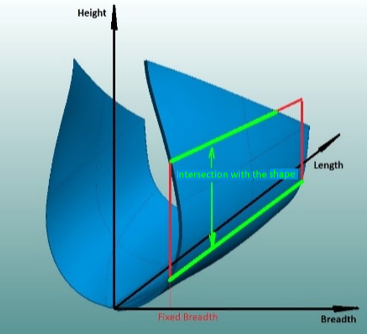
The relation line is defined as the intersection of the fixed value plane with the hull shape.
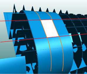
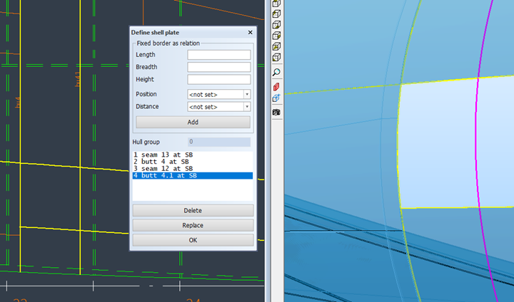
In the image above, the shell plate presented in white has four fixed border relations, two in breadth and two in length.
Defining shell plate relations
Define the shell plate relations one by one either by indicating hull lines in the graphical window or by defining a fixed value border. You must define the relations in counter-clockwise order.
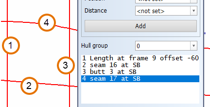
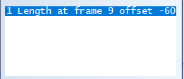
In the image above, the first relation has been defined as a fixed border relation in length direction.
To define a fixed value border, enter the position of the border in length, breadth, or height, and then click Add or press Enter. You can also select a grid line or grid value in the graphical window to fill in a field. The border is added to the relations list.
-
The fixed value in length is a frame number with a possible offset.
-
The fixed value in breadth or height is a grid value with a possible offset, or an absolute value in mm. The following are examples of valid values: B5.4 (for Breadth), H10-250 (for Height).
-
Position – You can select to limit the fixed value border to Starboard or Portside only. If not set, the area settings of the view define the limitation. The area settings are defined in Drawing Properties.
-
Distance – In case the fixed value border intersects with the shell in two points, you can select whether the Nearest or Farthest intersection in the view direction is used as the relation. If not set, both intersections are used as relations.
 Show/hide image
In the image above, fixed breadth is used. In top view, the upper intersection one is the nearest one, and the lower intersection is the farthest one.
Hull group – Select the hull group. The first hull group is the default selection. The relation lines must belong to the same hull group.
All the defined relations are shown in the relations list in the order they were added.
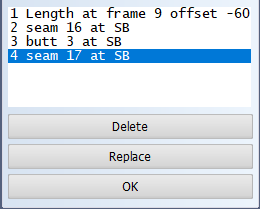
Selecting a relation briefly highlights it in the graphical window. You can replace or delete any relation by selecting it and clicking Replace or Delete, respectively.
-
Replacing a relation: Select the relation to be replaced, and either indicate the replacing relation in the graphical window, or define a fixed value border. The Add button changes to Insert. Click Insert to replace the relation.
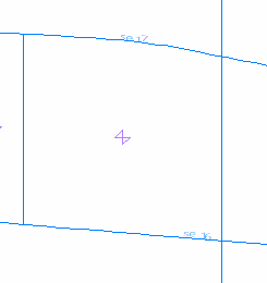
Once you have defined all the relations, click OK to save the shell plate. A cross symbol appears within the plate contour showing the shell plate's center of gravity.