Property grid
The property grid allows you to easily see and modify properties of all aspects of the weld lines currently selected in the Weld list.
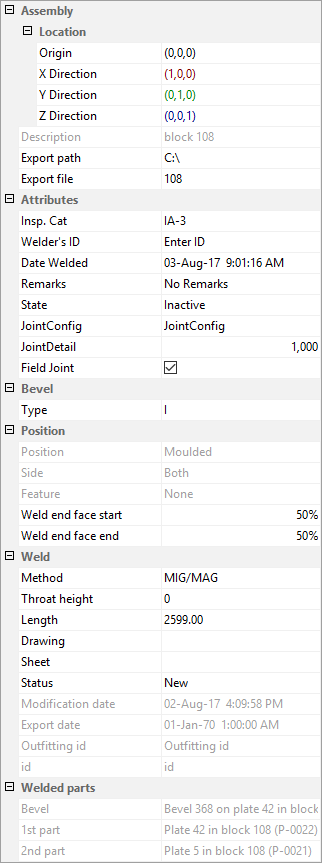
The contents of the items in the property grid will be displayed when they are applicable for all of the items selected in the Weld list, otherwise it will be empty. It is not possible to edit frozen items.
Assembly
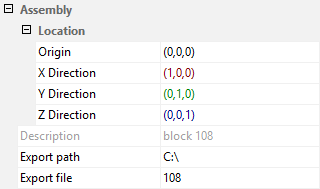
The properties in this category depend on the assembly selected in the Tree structure.
- Origin
- X Direction
- Y Direction
- Z Direction
The location and orientation of an assembly must be known when an assembly of parts has to be exported as one element to welding robot software. Weld Manager will export the welding data according to the orientation specified here so that it will be handled properly by a welding robot.
The origin of each assembly can be defined and displayed using the weld manager:
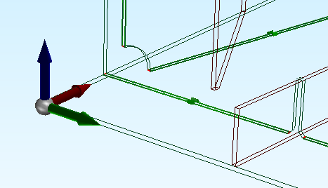
Both the origin and its orientation can be defined either by indicating a point on a part or by entering the coordinates in the property grid. The same applies for the directions of the axes.
Setting the location properties, origin and directions is performed by clicking the button  next to the value in the property grid for one of the axes and then indicating a 3D point which that axis should point to, starting from the defined origin.
The remaining fields within assembly are:
Description – A description of the selected assembly created according to the configuration.
Export path – The folder which the assembly will be exported to. This path can be built up from logistical values of the assembly according to the configuration or set manually. The export path can be set in System Management > Import/Export > Weld Manager > Output Directory. If the output directory is set in System Management, the export path cannot be manually set here, unless it was manually set here previously.
Export file – The name of the file which the assembly will be exported to. This name can be built up from logistical values of the assembly according to the configuration.
For each Work Breakdown Structure and location, a step file will be created which can be used as input for welding robot software.
Attributes
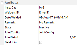
The values of any user-defined attributes can be modified here. These attributes are defined in either the Weld Manager configuration file or in System Management > Construction > Welds/Bevels > Weld Attributes.
Bevel
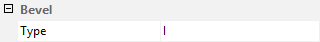
The bevel properties of the selected weld are displayed in this category. Only the bevel type is listed here.
Since the relationship between the weld and the bevel attribute is not directly dependent, modifications to the weld are not synchronized with the underlying bevel attribute. This means that recalculation or modification of bevels will remove any manually specified changes.
Position
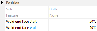
The properties within the position section are:
Side – Indicates which side, in the relation to the plane of construction, the weld is positioned upon (molded and/or thickness side).
Feature – Shows which weld features, if any, are present. See Weld features.
Weld end face start and Weld end face end – Percentage of face welding for the start and the end of the weld. See Weld faces.
Weld
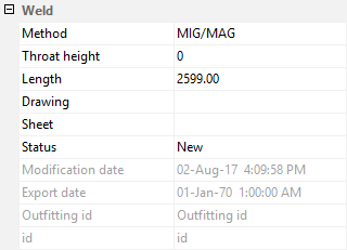
The properties of the selected weld are listed in the Weld category.
Method – Specifies the weld method to be used from the following options, which can be modified in System Management > Construction > Welds/Bevels > Weld Codes > Welding Codes, Second Part.
- MIG/MAG (Metal inert gas / Metal active gas)
- TIG (Tungsten inert gas)
- ARC (Arc welding)
- SAW (Submerged arc welding)
- SMAW (Shielded metal arc welding)
- Chain MIG/MAG
- Chain TIG
- Chain ARC
- Chain SAW
- Chain SMAW
Throat height – Specifies the throat height of the weld
Length – Specifies the length of the weld
Drawing – Specifies the name of the drawing where the weld appears
Sheet – Specifies the name of the sheet drawing where the weld appears
Status – Specifies the status of the weld. The status of the weld is also represented by an overlaid icon in both the list and the tree views. The options are:
- New

- Skipped

- Welded

- Misplaced

- Locked

Modification date – Specifies the date when the weld was last modified.
Export date – Specifies the date when the weld was last exported
Outfitting id – Specifies the CADMATIC Object ID
id – Specifies the Hull weld ID
The properties Weld type, Throat height and Status can be modified but the rest are fixed. Links next to Drawing and Sheet can be used to open the drawing or sheet drawing in 3D-Contek, when these drawings are available. The contents in this section are updated after a drawing or sheet with weld line information is saved.
Setting a weld line to Locked ensures that it will not be overwritten and any specific properties that it has will remain while weld lines are updated. This means that the information associated with locked weld lines can be out of date and not synchronized with construction. Locked lines will not be displayed in drawings once the drawing is updated.
Welded parts
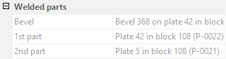
The parts that are being joined together by the weld, currently selected in the Weld list, are mentioned here, as well as the bevel between them.