Defining weld lines for cutouts and lugs
The type file for cutouts and lugs can include bevel information for welds.
A connection type can be specified for each segment of the defined shape. Each connection type can have its own bevel and weld information by specifying a predefined bevel used for the connection.
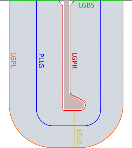
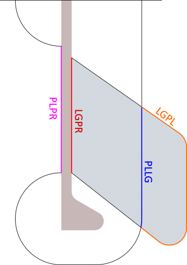
There are six connection types, each having a specific keyword (PLPR, PLLG, LGPR, LGPL, LGBS, LGLG):
-
Plate-to- profile (PLPR)
-
Plate-to-lug (PLLG)*
The PLLG keyword is also valid for profile-to-lug connections, and in beveling the system handles profile-to-lug connections similar to plate-to-lug connections.
-
Lug-to-profile (LGPR)
-
Lug-to-plate (LGPL)*
-
Lug-to-base (LGBS)
-
Lug-to-lug (LGLG)*
* The keywords for these connections can be left out from the type file. The system can automatically determine the connections of these keywords based on the other connections, and will do so for those specific connection(s) whose keyword is not found in the type file. This requires however that a valid predefined bevel number for the connection is specified on the W Line of the cutout type file. See W line below.
Each line in the type file of a cutout or lug which specifies the Shape definition of a line or an arc can be extended with one of these keywords. Adding a keyword indicates the type of the connection that the segment has with another part. This is to manually control precisely which area of a part should connect to another part.
If the connection should only apply to part of the segment, one or two additional values can be specified after the keyword in the type file line. These values specify a distance from the start of the segment toward the end of the segment.
- The first value indicates where the connection should begin along the line or arc.
- The second value indicates where the connection should end.
- If there are no values given after the keyword, the complete line or arc is included in the connection.
- If only one value is given, this is the start of the section that should be included in the connection.
The distances can be specified either as absolute values, or as fractions of the length of the segment (relative values).
- To specify an absolute value, enter the value in mm (e.g. 2.0). Optionally, an A prefix can be used to make it more obvious that the value is absolute (e.g. A2.0), but doing so will not affect the value itself.
- To specify a relative value, enter an F and then a fractional value in the range of zero to one. For example, the value F0.5 causes the start or end point of the connection to be precisely halfway along the segment.
Below are some example lines and their results:
-
VA=0
VB=0.75
L x1 y1 x2 y2 LGPR FVA FVB
The connection between a lug and profile would be specified as the first three quarters of a line between x1 y1 and x2 y2. -
C x3 y3 r3 LGPL F0.5
The connection between a lug and a plate would be specified as the second half of the arc centered at x3 y3 with a radius of r3. -
LCOLL x4 y4 x5 y5 LGBS 10.0
The connection between a lug and a base would be specified from 10.0 mm after x4 y4 until the point x5 y5 would be specified in the coding but not in the drawing, see Lugs to small part. -
L x6 y6 x7 y7 PLPR
The connection between a plate and a profile runs the entire length of the line between x6 y6 and x7 y7.
W line
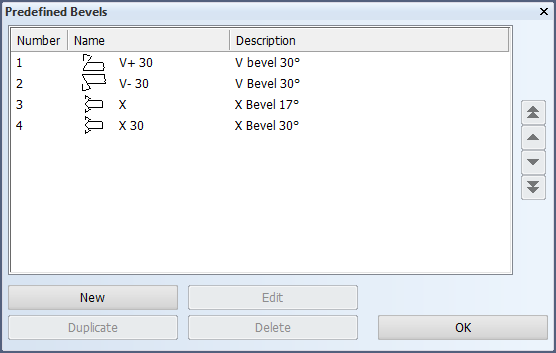
The six connection types can be linked to a predefined bevel using the so called W line (lug Line) in the type file. On the W line, after the character W, values from the 4th value to the 9th value are considered the numbers of the predefined bevels used by PLPR, PLLG, LGPR, LGPL, LGBS and LGLG, respectively.
For example:
W t= GR-A 3 3 2 1 2 3 4
The predefined bevel information on the W Line can only be added in a cutout type file.
To apply different properties for different situations, multiple W Lines with conditional statements can be used in a type file. See Using conditional statements with the W line for more information.
The numbers mentioned on the W Line are those of the predefined bevels, as shown in the System Management application in Construction > Welds/Bevels > Predefined Bevels, Number column.
When a valid predefined bevel number for a PLLG, LGPL or LGLG connection is specified on the W Line, but the keyword is omitted from the type file, the connection is automatically determined by the system based on the other connections.
Standard reference directions
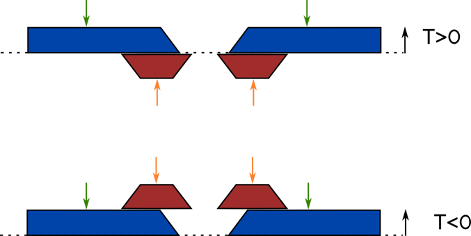
The system assumes the following standard directions for reference. These are important to consider when defining bevel information.
- For cutouts, the default view direction is toward the thickness side of the plate (green arrows in the image below).
- For lugs, the default direction is toward the side of the plate where the lug is positioned (orange arrows in the image below).
T>0 means that the lug is defined on the molded side of the plate. T<0 means that the lug is defined on the thickness side of the plate. T is the lug thickness that is defined in the cutout type file.
In the image below, the T>0 and T<0 cases are illustrated using V+ bevels for both the cutouts (blue) and the lugs (red).
Weld properties
The welding properties of cutouts and corner / draining holes can be influenced by their type files. Dedicated WELD lines can be specified in the type file to specify the weld properties. The following keywords can be used on these lines. The keywords apply to the value placed before them.
- PDB
The number of the predefined bevel which should be applied to the contour. - WMETHOD
The number of the weld method to be applied to the contour. This can be used to make a draining hole a weld stopper for example. - THROAT
The throat height of the weld. A value of -1 results in the system calculating the throat height automatically according to the Weld factor rules. - CRNR1, CRNR2
The location of the weld face where the weld should start (CRNR1) or end (CRNR2). These values are defined using a fractional value of the length of the weld face.
An example of weld properties being defined over multiple WELD lines within a type file:
WELD 96 WMETHOD -1.0 THROAT
WELD 0.5 CRNR1 0 CRNR2
WELD 3 PDB