Objects
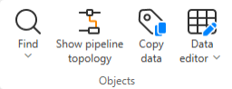
On the Data tab, the Objects group includes the following tools.
Find

In the Objects group, the Find menu includes the following commands.
Find objects (Alt+F) | Find text | Highlight line | Highlight pipeline by name | Highlight system by name | Highlight linked objects
Find objects (Alt+F)
Select Data tab > Objects group > Find objects to open the Find Objects dialog where you can search for objects from the active diagram or from all diagrams.
You can customize the column layout by clicking Columns. However, adding many columns may affect the search speed.

-
Search from – Select Active diagram (default) or All diagrams.
-
Search method – Select what to search for: PosID, Line name, System name, or Object ID.
-
Search string – Enter the search string. You can use the asterisk character as a wildcard, either within the search phrase (PosID: 00*) or on its own to list all items in the given category (PosID: *).
-
Only in selected subtable – Select this option and then select the required subtable to limit the search to that subtable. This may improve the performance, especially in large projects where searching through all diagrams can take a considerable amount of time, but also when searching through a single, very large diagram.
-
Search – Select this to perform the search. When the search completes, you can select a search result to highlight and zoom to the found object, if located in the active diagram.
-
Query Object – Opens a dialog displaying the database data of the selected object.
-
Edit Diagram – Opens the diagram where the selected object is located in edit mode, unless the diagram is already open in browse mode.
-
Browse Diagram – Opens the diagram where the selected object is located in browse mode, unless the diagram is already open in edit mode.
Find text
Select Data tab > Objects group > Find text to open the Find Text dialog where you can search for a text string from drafting texts, labels, and/or reference drawings.

-
Search text – Enter the text to be found.
- The search phrase can be found from any part of a text string. For example, the search text "001" can find "P001" and "P001A".
- You can use regular expressions. For example, the search text "P[0-9,A-Z]" can find "P001" and "P001A".
-
Search options – Specify where to find the text. Select the Match case option if you want the search to be case-sensitive.
-
Find – Performs the search.
-
Click a search result to zoom to the found text in the diagram.
-
You can temporarily hide the search tool by clicking the diagram. Press Esc to show the search tool again.
Highlight line
Select Data tab > Objects group > Highlight line to highlight a whole line when one of its parts is selected. The name of the highlighted line is displayed in the status bar.
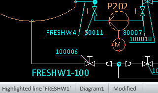
Press Esc to stop highlighting the selected line. You can select another line to be highlighted, or press Esc again to exit the highlighting tool.
Highlight pipeline by name
Select Data tab > Objects group > Highlight pipeline by name to open a dialog where you can select a pipeline to be highlighted in the active diagram.

Press Esc to exit the highlighting tool.
Highlight system by name
Select Data tab > Objects group > Highlight system by name to open a dialog where you can select a system whose objects to highlight in the active diagram.

Press Esc to exit the highlighting tool.
Highlight linked objects
Select Data tab > Objects group > Highlight linked objects to set the color of linked objects (objects with the same Position ID) in the active diagram to white. All other objects are dimmed.
This allows seeing whether objects have multiple instances in the active diagram or share their Position ID with objects in other diagrams.
For more information on linked objects, see Manage linked objects.
Press Esc to exit the highlighting tool.
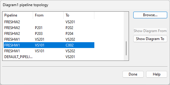
Show pipeline topology

Select Data tab > Objects group > Show pipeline topology to open a dialog that lists the pipelines in the active diagram and the objects at the start and/or end of a pipeline.
You can click Browse to browse the objects in the selected location.
If a pipeline is coming from or continues in another diagram, clicking Show Diagram From or Show Diagram To opens that other diagram and highlights the connected entities.
Copy data

You can copy data from one diagram object to other objects. You can copy data between different kinds of objects if they have matching fields in the database. If some of the target objects do not have all the fields you are copying, then that part of the data is skipped.
Do the following:
-
Select Data tab > Objects group > Copy data. The Select Source dialog opens.
-
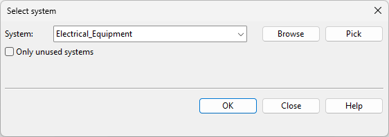
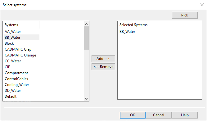
Select the data source: Object, System, Pipeline, Instrument Tag, or Electric Circuit.
-
Depending on what you chose as the source, you are prompted to pick an object or a dialog opens for selecting a system, pipeline, tag, or circuit.
-
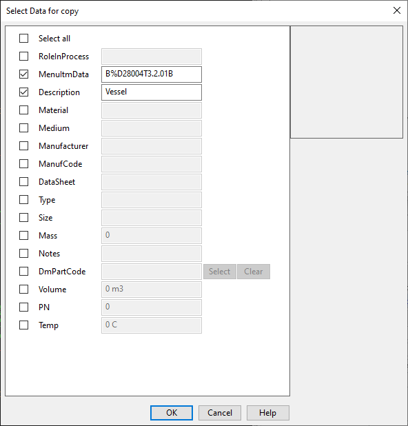
In the Select Data for copy dialog, select which values to copy from the specified source and click OK.
-
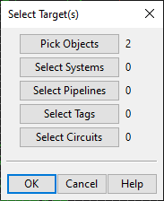
In the Select Target(s) dialog, select to which targets to apply the data and click OK.
 Show/hide image
In this example, the data is to be copied to two objects.
-
Depending on what you chose as the target, you are prompted to pick the target objects or a dialog opens for selecting the target systems, pipelines, or tags.
-
In the Select target(s) dialog, click OK to perform the copying.

After this, the labels are automatically updated. However, if you copy e.g. Nominal Size from one pipeline to another, the labels are only updated when you save the diagram or perform some other command that is set to update the labels, as described in Automatic Update. You can update labels manually by selecting Home > Label > Update > All labels.
Data editor
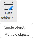
Use the Data editor tools to edit the data that diagram objects have in the SQL database.
Single object | Multiple objects
Single object
Select this command to edit the SQL data of objects in the active diagram, one object at a time.
Prerequisites
-
To pre-fill fields in the editor, the set_defaults script must contain definitions for CHECK_DATA and CHECK_DYNPANEL_FIELDS. You can find example definitions in the set_defaults script of the CADMATIC example project. For general information on this setup script, see the 'set_defaults' script.
Do the following:
-
Select Data tab > Objects group > Data editor > Single object.
-
Select the objects whose data you want to edit from the active diagram, and press Enter. The Edit object data dialog opens, displaying the data of the first object you selected.
-
Fill in and edit values as required.
-
Click OK to accept the changes. If you entered a new Position ID and the ID is already in use, you are prompted to generate a new ID for it.
-
If you selected to edit more than one diagram object, the data of the next object you selected opens. Fill in and edit values until all the objects you selected have been processed.
Tip: You can edit object data also via the Property Pane.
Edit object data
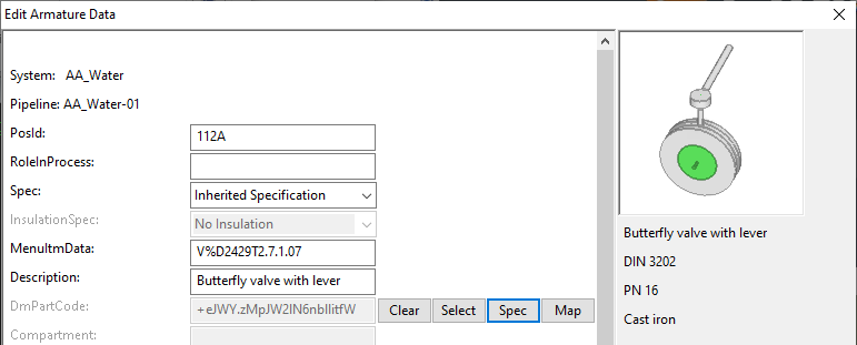
In the Edit […] Data dialog, you can manage the data that a diagram object has in the SQL database.
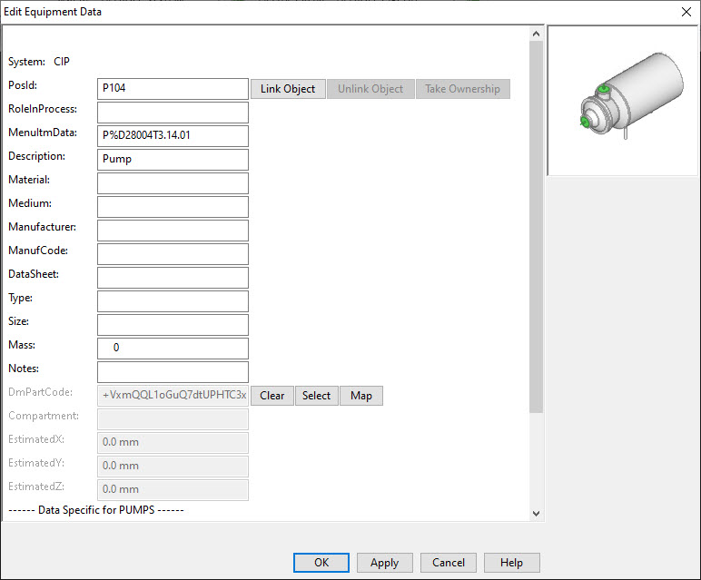
The title of the dialog reflects the object type, so it can be one of the following:
- Edit Armature Data
- Edit Equipment Data
- Edit Instrument Data
- Edit Terminator Data
All objects, regardless of their type, have at least these fields that you can edit:
|
PosId |
Position ID, usually automatically generated. |
|
Prefix and lookup key, specific to the symbol. |
|
|
Description |
Description of the object, automatically generated from MenuItmData. |
In addition, there can be fields that are common for all objects of the same type, such as fields that all Equipment objects have.
Then, there are fields that are shared by the object subtype, such as fields that are specific to Equipment whose subtype is Valve.
In most fields, you can enter the required value by typing. Some fields also have special buttons for managing the value.
PosId field

The PosId field stores the Position ID of the diagram object. Typically, the ID is object-specific and automatically generated, so that opening the database card of a new object shows the ID that the program has assigned to it. The project administrator can select whether the IDs are generated, and how they are generated, as described in Administrating P&ID.
For example, the CADMATIC example project has been set up to use the combination of the prefix in the "MenuItmData" field and a 3-digit ordinal number to generate the PosId for objects whose type is Equipment or Armature.
Even if Position IDs are automatically generated, in the "PosId" field you can type a new ID for the current diagram object. If the given ID is already in use, you are prompted to generate a new one, so that this object's data can be stored in a separate database record.
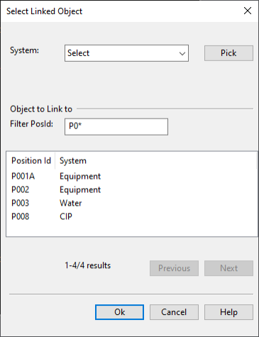
Select Linked Object
Instead of generating or typing a new Position ID, you can link the current diagram object to an existing Position ID. This allows the linked objects to share the same data, and you can modify the data via any of the linked objects. Only Position IDs that have been checked in to COS can be selected for linking.
In the database card, use these buttons to manage the linking:
-
Link Object – Opens the Select Linked Object dialog where you can link the current diagram object to another diagram object of the same type. After this, the linked diagram objects use the same Position ID and data.
The dialog lists the Position IDs that exist in COS and can be linked to the current object.
You can filter the list to find the required Position ID:
-
Filter by system. Select a system from the list, or use the Pick tool to pick the system from another object.
-
Filter by pipeline or electrical circuit, if applicable.
-
Enter a filter string in the Filter PosId field. You can use the asterisk character '*' as a wildcard.
If the list is long, you can use the Previous/Next buttons to browse the list.
Once you locate the required position ID, select it from the list and click Ok.
Tip: You can use the 'Colors: By Linked Object' color-coding mode to see which objects in the current diagram are linked, as described in Colors. See also Manage linked objects.
-
-
Unlink Object – Unlinks the current diagram object. You must enter a new PosId for the object. After this, the current object will have its own data in the database, instead of using shared data.
-
Take Ownership – Editing the data of a diagram object sets the ownership of the data to that object. If you want to edit the data of linked objects and the current owner is some other object, use this command to take the ownership from that other object. Note that ownership cannot be transferred if the current owner has unsaved changes.
Tip: You can perform the above actions also from the Property Pane.
DmPartCode field

The DmPartCode field stores the OID of the 3D component assigned to the diagram object.
Use these buttons to manage the part code information:
-
Clear – Removes the 3D component assignment from the diagram object.
-
Select – Opens the COS object browser for selecting the component to use in the 3D model.
-
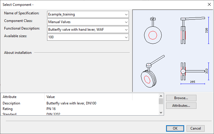
Spec – Opens the Select Component dialog for selecting the component to use from the applicable specification. If Nominal Size is defined, only parts that match the given size are listed; otherwise, parts of all sizes are listed.
After using Select or Spec to select the component to use in the 3D model, the component's preview image, Description, and main attributes (when selected from specification) are displayed in the side pane.
-
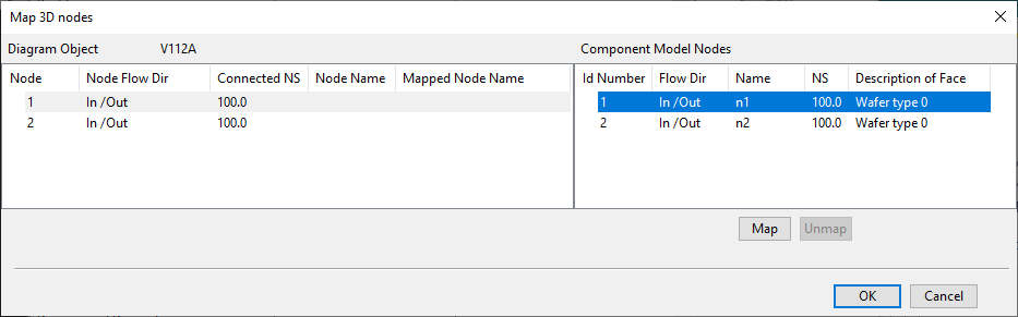
Map – Opens the Map 3D nodes dialog where you can map the nodes of the diagram object to the nodes of the associated 3D model object. For details, see Mapping nodes between P&I diagram and the 3D model.
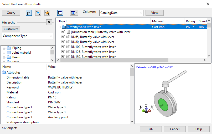
Tip: You can perform the above actions also from the Property Pane.
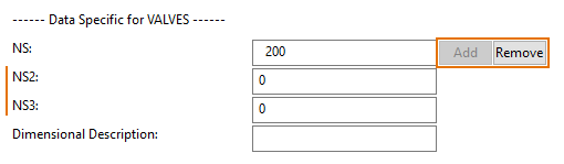
NS fields
Objects of type Armature have one Nominal Size field, NS, by default. You can use the Add button to add more NS fields (NS2, NS3…), if needed.
About string type fields
If the type of a database field is wide string (WSTRING), when you are adding a value to the field you cannot use more than 1023 characters.
In the past, however, also longer strings were allowed, and therefore the functionality of the editor depends on the length of the existing value:
- If the field contains a value that consists of 1–1023 characters, you can edit the value in the database editor, as usual.
- If the field contains 1024 characters or more, the field is not displayed in the database editor at all.
Multiple objects
Select this command to edit the SQL data of objects in the open diagrams, one or more objects at a time.
Prerequisites
-
To pre-fill fields in the editor, the set_defaults script must contain definitions for CHECK_DATA_MULTI_EDIT and CHECK_DYNPANEL_FIELDS_MULTI_EDIT. You can find example definitions in the set_defaults script of the CADMATIC example project. For general information on this setup script, see the 'set_defaults' script.
Do the following:
-
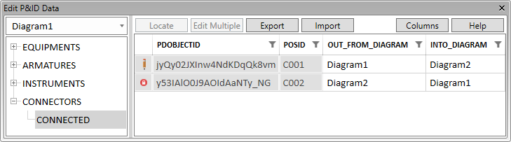
Select Data tab > Objects group > Data editor > Multiple objects. The Edit P&ID Data dialog opens.
-
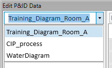
Select which of the currently open diagrams to edit. Selecting a diagram from this list (or from elsewhere in the application) sets that diagram as the active diagram.
-
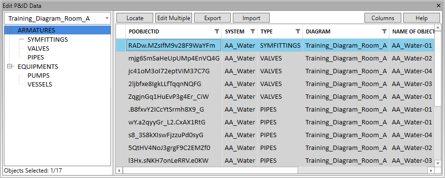
In the object type tree, select the type or sub-type to edit. The objects in that category are listed in the table view, and the columns that cannot be edited are dimmed. The first column indicates availability, and it can show if the object is being edited by someone else
 , being edited by you
  , or not available due to replication
  . You can take ownership, where possible, by clicking Take ownership.
 -
Select what information to show in the dialog.
-
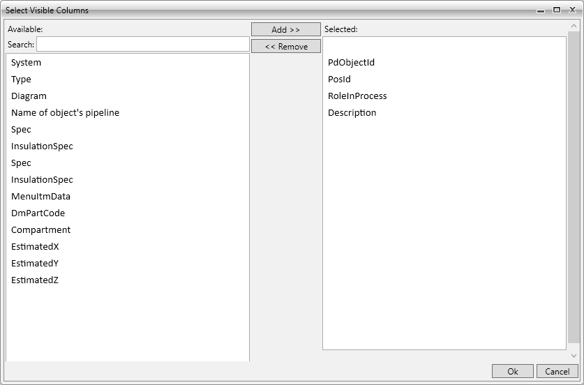
Use the Columns tool to add or remove columns. Only those columns that all the objects have in common can be displayed.
-
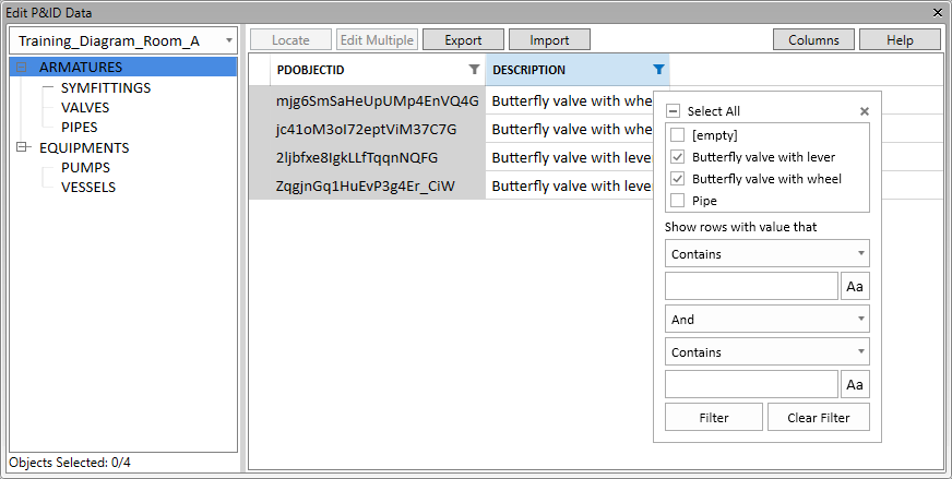
Use the column header filters
 to filter the table by the column contents.
-
-
To see where an object is located in the active diagram, select the object from the list and click Locate.
-
To edit a single value of a single diagram object, select the field and edit the value.
-
To edit one or more values of one or more diagram objects, do the following:
-
Hold down Ctrl or Shift and select the rows you want to edit, or use Ctrl+A to select all rows.
-
Click Edit. The Edit Multiple Rows dialog opens.
-
Fill in the values, and click Ok.
-
-
To export data to a Microsoft Excel file, do the following:
-
In the left pane, select the table view to export.
-
Use the column selector and column filters to define what data to include in the export.
-
Click Export.
-
In the export dialog, enter a file name, select the file type (.xlsx or .xlsm), select the export location, and click Save.
-
-
To import data from a Microsoft Excel file, do the following:
Show/hide details
-
Select the table view that contains the diagram objects to update.
-
Set the column filters so that the objects are visible.
-
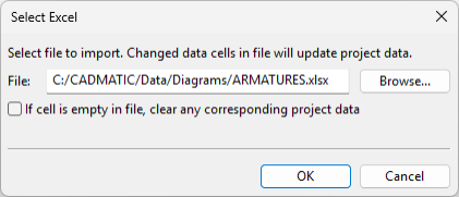
Click Import. The Select Excel dialog opens.
-
Select the file to import, select whether to clear values that are empty in the import file, and click Ok.
-
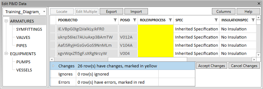
The table view highlights the fields that contain changes, and the pane below the table view lists messages from the import.
-
Changes – This section lists changes that can be accepted.
-
Ignores – This section lists changes that cannot be accepted because the target object is not visible in the table view. (This may be caused by use of filters in the table view.)
-
Errors – This section lists erroneous changes that cannot be accepted.
You can open a section that contains messages to see more information about the incoming data. If the messages indicate problems that you can fix by modifying the import data, edit the Excel file as required, and then re-import it.
-
-
Select how to proceed:
-
Click Accept Changes to accept the changes that are listed in the Changes category.
-
Click Cancel Changes to cancel the import.
-
-
-
To close the editor dialog, click the X button.
Tip: You can edit object data also via the Property Pane.