Show

On the Home tab, the Show group includes the following commands.
Panes

You can drag a pane by its title bar and then either allow the pane to float or dock the pane to the side or the bottom of the application window. When another pane already occupies the same place, you can dock the panes side-by-side or show them as tabs—also when they are floating. On-screen indicators show where the pane you are dragging can be docked.
To maximize the working area, you can set a pane to be automatically minimized when the focus is not in the pane. Note that you cannot drag a pane when auto-hiding is enabled.
Message Pane | Property Pane | Template Pane | Markups Pane
Message Pane
Select Home tab > Show group > Panes > Message Pane to show or hide the Messages pane.
You can also toggle it on or off by clicking the Show message pane button  (no new messages) or
  (new messages) in the application status bar.
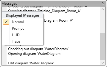
The Messages pane can display information such as names of commands you select, actions the program requests from you, and error messages. To control which messages are shown, click the arrow button on the left and select options from the list:
- Normal – This mandatory option provides a minimum level of messaging.
- Prompt – Select this option to display program prompts in the message pane.
- HUD – Select this option to display HUD messages in the message pane.
- Trace – Select this option to display very detailed messages.
Property Pane
Select Home tab > Show group > Panes > Property Pane to show or hide the Properties pane.
Initially, the property pane docks to the right side of the application window. You can switch between docking mode and floating mode via the context menu of the title bar. When docked, you can drag the pane by its title bar to dock it to another side of the application window or to stack it with another pane.
You can export the contents of all tabs into a Microsoft Excel file (.xlsx) or macro-enabled Microsoft Excel file (.xlsm) by clicking  or by pressing Ctrl+E within a tab.
The Properties pane can display the following tabs, depending on the selected diagram object.
Basic information | Connections | Component model | eShare data | EDM data
Basic information
The Basic Information tab displays and allows editing the data of the selected diagram object.
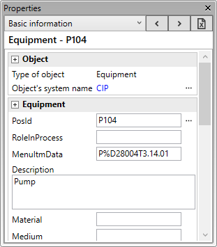
Some object data is static, such as various names and attribute values, while other data is dynamically generated, such as the Pipe data section, which displays outer diameter, wall thickness, and pipe material based on the specification and functional description.
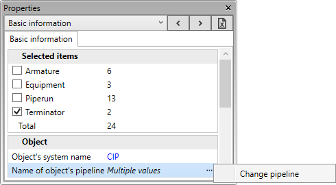
Some of the basic information can also be edited when multiple diagram objects are selected. When the selected objects represent several object types, you can use the Selected items section to choose which object types are affected by editing.
Note: To edit the value of a field that multiple object types have, in the database tables the fields must have the same name, same unit, same unit format, same range, and same maximum length.
Tip: You can edit multiple objects also via Data tab > Objects group > Data editor > Multiple objects.
For more information on editing the values in this pane, see Property links.
Selecting an eShare markup from the Markups Pane displays its details in the property pane.
Connections
The Connections tab displays the connection nodes of the selected diagram object. You can edit the nodes as you can with the Modify and Propagate tools.
While working on this tab, the node names and numbers are displayed in the diagram using the highlight color defined in the Colors settings.

Component model
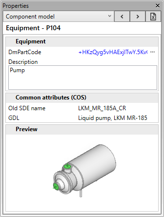
The Component model tab displays information on the component model that the selected diagram object is linked to. Opening this tab loads the component data from the COS database.
Clicking the 'DmPartCode' value displays the component model in an object browser dialog.
For more information on editing the values in this pane, see Property links.
eShare data
The eShare data tab displays P&ID related object data that is stored in CADMATIC eShare. Opening this tab loads the data of the currently selected diagram object from eShare, if the object has a position ID that can be found in eShare.
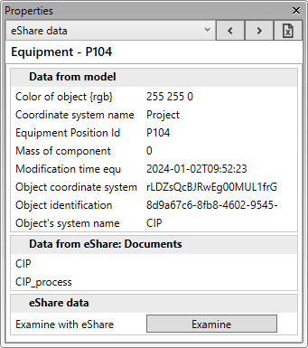
If you have eShare, you can click Examine to open the model object in eShare in examination mode.
See also Examine with eShare and Working with CADMATIC eShare.
EDM data
The EDM data tab displays the external data of the selected object.

See also View EDM data.
Property links
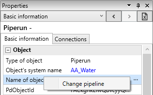
The top of the Properties pane displays the type and name of the selected entity. Blue property values link to related entity properties, such as the pipeline of the selected object. When you have viewed the properties of more than one diagram object or related entity, use the arrow buttons to revisit their properties while keeping the same tab selected. If the next object does not support the active tab, the basic information tab is displayed instead.

Some properties provide access to related settings:
-
You can change the system, pipeline, instrument tag, or electric circuit of an object by selecting … and then Change system, Change pipeline, Change tag, or Change circuit, respectively.
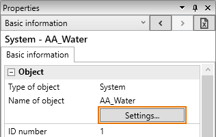
-
You can access the settings of a system, pipeline, instrument tag, or electric circuit by clicking Settings.
-
In the PosId row, you can select … and then:
-
Generate position ID – Assigns the next free position ID to the object. See Generate PosID.
-
Link object – Opens the Select Linked Object dialog where you can link the current diagram object to another diagram object of the same type. After this, the linked diagram objects use the same position ID and data.
-
Unlink object – Unlinks the current diagram object. You must enter a new PosId for the object. After this, the current object will have its own data in the database, instead of using shared data.
-
Take ownership – Editing the data of a diagram object sets the ownership of the data to that object. If you want to edit the data of linked objects and the current owner is some other object, use this command to take the ownership from that other object. Note that ownership cannot be transferred if the current owner has unsaved changes.
-
-
In the Connector section:
-
You can generate a position ID for a connector: in the PosId row, select … and then Generate position ID.
-
You can link a connector to a connector in another diagram.
 Show/hide details
-
In the Out_From_Diagram or Into_Diagram field, select … > Link diagram.

-
In the Select Target of Connector dialog, select the target connector and click Done.
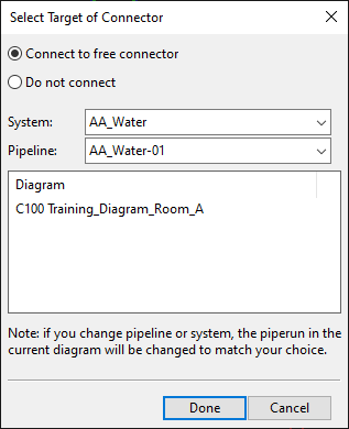
-
Save the diagram to COS.
-
-
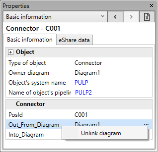
You can remove the link between two connectors.
Show/hide details
-
In the Out_From_Diagram or Into_Diagram field, select … and then Unlink diagram.
-
Save the diagram to COS.
-
See also Insert connectors.
-
-
In the DmPartCode row, you can select … and then:
-
Clear field – Removes the current part code.
-
Select – Allows changing the component reference.
-
Select from specification – Allows changing the component reference to another component allowed in the specification.
-
Map object nodes – Allows changing the node mappings. See Mapping nodes between P&I diagram and the 3D model.
-
-
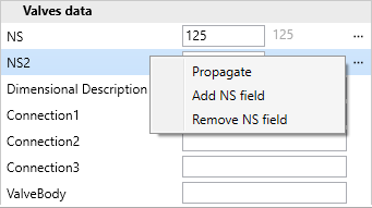
In the NS rows of armature:
-
You can Propagate the current NS value to all connected pipe runs that start from a node using the same NS field (NS, NS2, or NS3).
-
You can add or remove NS fields. This might be needed for reducing valves or release valves. Removal is only possible when the value is 0.
Note: Parts that always have two nominal sizes should have them defined in the nodes of the 2D symbol. Then the NS fields are automatically correct in the sub-table. A sub-table can have a maximum of five different nominal sizes, and the additional sizes must be defined in the database using the field names NS2 – NS5.
-
Template Pane
Select Home tab > Show group > Panes > Template Pane to show or hide the Object templates pane.
This pane includes:
Diagram object assignment tools
In the Select Objects pane, use the drop-down lists to specify system and line information for diagram objects.
-
System – Select whether to use the DEFAULT_SYSTEM, a specific system, or show a selection dialog, to assign a system to a piece of equipment.
-
Pipeline – Select whether to use the DEFAULT_PIPELINE, a specific pipeline, or show a selection dialog, to assign a pipeline to an armature, inline instrument (if included in System Default options and the instrument has a 'Pipeline' data field), or pipe run.
-
Instr. tag – Select whether to use the DEF_TAG, a specific tag, or show a selection dialog, to assign an instrument tag to an instrument or instrument line.
-
Circuit – Select whether to use the DEFAULT_CIRCUIT, a specific circuit, or show a selection dialog, to assign an electric circuit to a cable or electrical component.
Note: If a drop-down list does not have the entity you wish to select, choose the Ask User option.
Select  (Assign) and then one or more diagram objects to apply the associated setting to those objects.
Tip: Use the Objects connecting two points selection method to select all connected objects between two points in a pipeline, tag, or circuit.
Select … to access these commands:
-
Create – Allows creating a new entity of the given type, adding the new item to the respective drop-down list.
-
Create from template – Allows creating a new entity by using an existing entity as a template, adding the new item to the respective drop-down list.
-
Clean unused – Removes list items not used in the active diagram.
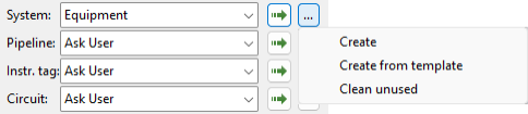
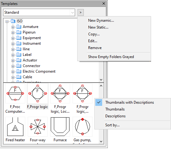
Diagram object template categories
In the Select Objects pane, the diagram object templates are arranged into hierarchical categories. You can browse the categories to find the object to insert into the active diagram.
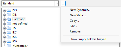
For administrators: You can customize the hierarchies by clicking … next to the hierarchy selection field and selecting the applicable option. For more information, see Hierarchy commands.
In the Select Objects pane, double-click a diagram object template to insert a new diagram object of that type into the active diagram.
Right-click the object list to select whether to list the templates as thumbnails, descriptions, or both, or to sort them by a specific attribute.
![]()
Tip: You can also use an object browser dialog for insertion of diagram objects—see Object.
Markups Pane
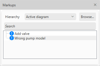
Select Home tab > Show group > Panes > Markups Pane to show or hide the Markups pane. If your environment is configured to access CADMATIC eShare, this pane lists markups that have been added to diagrams in eShare.
-
Hierarchy – Select whether to show markups from all diagrams or only from the active diagram.
-
Browse – Opens the Markups dialog for managing markups.
Show/hide details
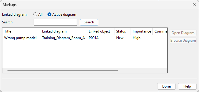
In the Markups dialog, you can do the following:
-
Linked diagram – Select whether to show markups from all diagrams or only the active diagram.
-
Search – Type a search string and press Enter to show only markups whose properties include the specified text. This search applies to all text columns.
-
Open Diagram – Open the diagram that contains the selected markup in edit mode.
-
Browse Diagram – Open the diagram that contains the selected markup in browse mode.
-
-
Search – Type a search string and press Enter to highlight matching items in the markup list. This search applies only to markup titles.
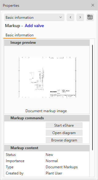
Selecting a markup from the Markups pane displays its details in the Property Pane—arrange the panes so that both are visible at the same time. In the property pane, you can do the following:
-
Start eShare – Open the diagram containing the markup in eShare (in web browser).
-
Open diagram – Open the diagram containing the markup for editing.
-
Browse diagram – Open the diagram containing the markup for browsing.
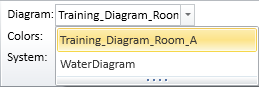
Diagram
In the Show group, the Diagram field shows 'No Active Diagram' if no diagrams are open, otherwise it shows the name of the currently active diagram. If you have several diagrams open, you can change the active diagram from the drop-down menu.
You can also change the active diagram from the Arrange Windows menu in the P&ID status bar. There you can also see whether each diagram has been opened in edit or browse mode.
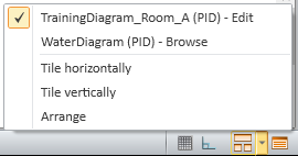
For more details on the status bar, see User interface.
Colors
In the Show group, the Colors field displays what is the current coloring mode of the active diagram. Opening a diagram sets the coloring mode to the default, which is 'By System', and you can select a different coloring mode from the drop-down list.
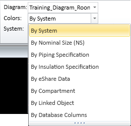
These coloring modes are available:
-
By System – Objects are colored according to their system. System colors are defined in File > Environment > Systems and lines.
-
By Nominal Size (NS) – Objects are colored according to their Nominal Size value.
Show/hide example
In this example, the colors make it easy to see that pipeline WAA0051 (NS=100) and valve V005 (NS=80) have different Nominal Size values.

-
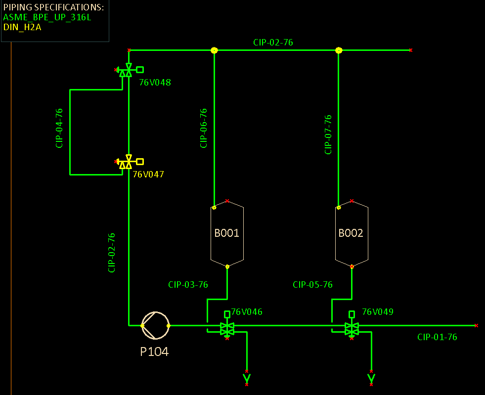
By Piping Specification – Objects are colored according to color definitions in piping specifications. If valves and pipe run parts use another specification than the first specification option from the pipeline, project administrator must add the required specification columns to the ARMATURES table—see ARMATURES.
Show/hide example
In this example, the colors show that all pipelines and valves use piping specification ASME_BPE_UP_316L except valve V047 which uses DIN_H2A.
-
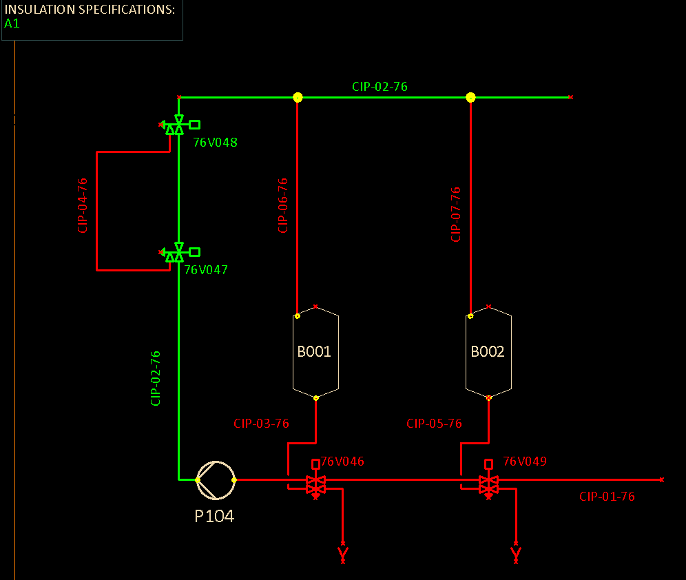
By Insulation Specification – Objects are colored according to color definitions in insulation specifications.
Show/hide example
In this example, the colors show that pipeline CIP-02 uses insulation specification A1 (green) and that the other pipelines do not use any insulation specification (red).
-
By eShare Data – Objects are colored according to an object categorization obtained from CADMATIC eShare. You can use this function when your Windows account is defined in the eShare user list and eShare project administrator has given your account permission to access the specified data.
Show/hide details
Selecting the By eShare Data option opens the Select Category dialog where you can select which eShare category to use for the coloring.
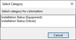
Note: From this list you should select an attribute category, Smart Point Type, or Status Tracking item defined in eShare that targets the following attributes: Equipment Position Id (.n5), Instrument Position Id (ipo) and Valve Position Id (vpo). All other selections are not applicable.
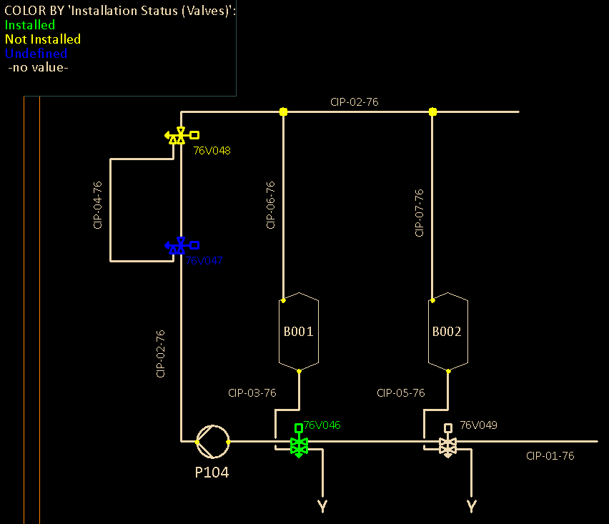
Selecting a category from the list colors the active diagram based on the general active colors functionality and the color palette of the project. P&ID does not get color definitions from eShare.
Show/hide example
In this example, the diagram makes it easy to see what is the installation status of each valve. Typically, the installation status is set on-site, using the CADMATIC eGo tablet application, and then uploaded from eGo to eShare.
-
By Compartment – Objects are colored according to compartment (if defined in the object data).
-
By Linked Object – When the same P&ID data object has multiple instances in the active diagram or in different diagrams, those object instances are linked, and this option allows you to easily see which objects in the active diagram are linked objects. The colors also indicate whether the linked object is owned by the active diagram or some other diagram. For more information on the linking, see Manage linked objects.